Iron and Steel
1 Introduction - Loads and Stresses
The principles of structural mechanics form the basis
for structural calculations, no matter what the materials and systems
employed. A few of the principles are set out below - the terms we have
used are those which were familiar to engineers working during the mid
19th and early part of the 20th centuries. Remember that in the very
early days of iron column and beam design (1790s to 1830s) much of this
was new and engineers experimented by trial and error. The design of
columns and beams changed from project to project as engineers learnt
from their mistakes, built on their successes, developed new ideas and
discovered what other designers were doing (patents were often taken out
to try and prevent this). This section explains:
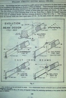
This section is not meant to be a detailed explanation of structural principles but a very brief introduction to some of the problems faced by Georgian and Victorian engineers. It's mostly based on late Victorian textbooks and partly on Modern Practical Building by Harry Bryant Newbold; first published in 1934 by Caxton. Specific aspects of the design and sizing of early steel beams can be found in the Section on Steel Frames - Early 20th century. The image on the right (regrettably the source is unknown) shows the development of William Strutt's beam designs for fireproof floors. Unfortunately, as yet, we don't have a larger image of this. |
 |
| The combined weight of roofs, floors, walls etc are called dead loads. These loads do not change once the building is complete. Dead loads can be calculated from the known weights per unit of area or volume for the various materials used. The weight of furniture, machinery, equipment and the people inside a building make up the live loads. These loads can vary in position and quantity. Live loads are not usually calculated but based on standard tables which provide figures for different types of building; offices, shops, schools, houses etc. The dead and live loads produce stresses in the building structure. During the period we are concerned with in this topic (roughly late 18th to early 19th centuries) stress was defined as the load per unit cross sectional area and as calculated in tons per square inch. Much of this topic is about the evolution of commercial buildings and much of it relies on extracts from contemporary books and catalogues. We have, therefore, decided to leave the Imperial units unaltered - converting them all to metric units would be a fairly tedious exercise with little benefit to the reader. | |
| Compressive stress: the load bearing downwards on the vertical axis
of a column - this tends to crush the fibres which make up the column.
Columns constructed in traditional materials such as stone and brick
tend to be of large cross-sectional size relative to their length. A
column in cast iron can be much more slender due to cast iron's high
compressive strength. Tensile stress: a load suspended at the end of wire produces tensile stress - it tends to tear apart the fibres. Shear stress: if two opposite forces act on a material and they are not quite in line the fibres can fail by a sliding action. A material cut by scissors is a simple example of shear failure. |
|
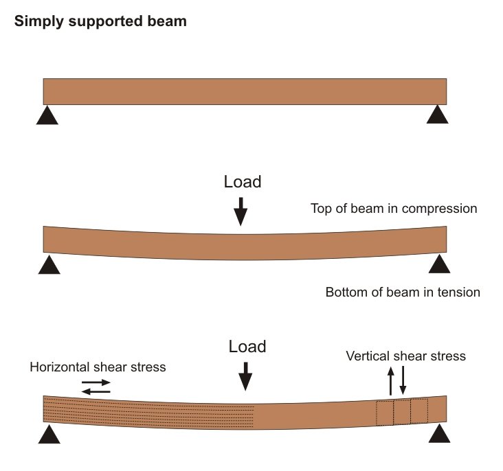 |
The graphic on the left shows a loaded beam and the
stresses which are produced by bending. As the beam bends the top of the
beam becomes slightly shorter and the bottom of the beam slightly
longer. The top of the beam is in compression and the bottom is in
tension; the stresses are greatest at the top and bottom edges, becoming
smaller and smaller as the middle of the beam is approached. Along the
neutral axis, which runs horizontally along the centre line of the beam,
there is neither compression nor tension. Vertical shear stress occurs due to the tendency of the beam to shear under load, particularly near each supported end. Horizontal shear stress is caused by the fibres trying to slide over each other as the top of the beam is shortened and the bottom lengthened. |
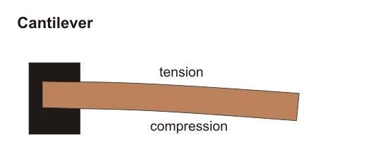 |
A cantilevered beam behaves in the opposite way. The top of the beam goes into tension and the bottom compression. |
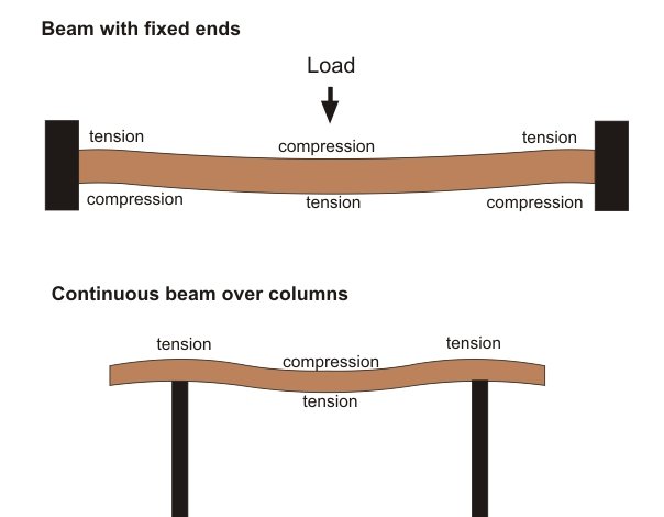 |
If a beam is supported at both ends and the ends are rigidly fixed
the behaviour of the beam is a bit more complex. The beam is less
inclined to bend than a beam with 'free' ends and, consequently, a beam
does not have to be so deep. In practice, however, it's not easy to
rigidly fix ends. Building a beam into a wall or simply bolting it to a
column usually gives a partial fixing.
If a beam is rigidly fixed to a column (sometimes called a continuous
connection) the saving in beam cost may be offset by the need for a
stronger column - because some of the beam's 'bending' is transferred
into the column. A 'bending moment' is an example
of an internal force ('shear' mentioned above is another one) that is
induced in a structure when loads are applied to that structure.
If a beam runs across the top of a column the top of the beam (i.e. the bit over the column) goes into tension - see left-hand graphic. |
| The early engineers learnt to cope with these stresses in various ways - some solutions were more successful than others. But first they had to understand the materials they were working with; the following sections explain the manufacture and use of cast iron, wrought iron and steel. Although engineers were quite innovative in some respects, i.e. the development of fireproof floors, in others they were quite conservative: for example traditional loadbearing masonry remained the norm for external walls until the early part of the 20th century. The 'pages' explain the manufacture and use of cast iron, wrought iron and steel. Other sections in this topic describe their evolution during the 19th and early 20th centuries. | |
except where acknowledged