![]()
1 Introduction - Loads and Stresses
2 Cast Iron - Manufacture
3 Cast Iron - Columns & Beams
4 Wrought Iron - Manufacture
5 Wrought Iron - Beams & Riveting
6 Early Steel Manufacture
The principles of structural mechanics form the basis
for structural calculations, no matter what the materials and systems
employed. A few of the principles are set out below - the terms we have
used are those which were familiar to engineers working during the mid
19th and early part of the 20th centuries. Remember that in the very
early days of iron column and beam design (1790s to 1830s) much of this
was new and engineers experimented by trial and error. The design of
columns and beams changed from project to project as engineers learnt
from their mistakes, built on their successes, developed new ideas and
discovered what other designers were doing (patents were often taken out
to try and prevent this). This section explains:
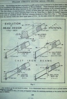
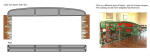
This section is not meant to be a detailed explanation of structural principles but a very brief introduction to some of the problems faced by Georgian and Victorian engineers. It's mostly based on late Victorian textbooks and partly on Modern Practical Building by Harry Bryant Newbold; first published in 1934 by Caxton. Specific aspects of the design and sizing of early steel beams can be found in the Section on Steel Frames - Early 20th century. The image on the right (regrettably the source is unknown) shows the development of William Strutt's beam designs for fireproof floors. Unfortunately, as yet, we don't have a larger image of this. |
 |
| The combined weight of roofs, floors, walls etc are called dead loads. These loads do not change once the building is complete. Dead loads can be calculated from the known weights per unit of area or volume for the various materials used. The weight of furniture, machinery, equipment and the people inside a building make up the live loads. These loads can vary in position and quantity. Live loads are not usually calculated but based on standard tables which provide figures for different types of building; offices, shops, schools, houses etc. The dead and live loads produce stresses in the building structure. During the period we are concerned with in this topic (roughly late 18th to early 19th centuries) stress was defined as the load per unit cross sectional area and as calculated in tons per square inch. Much of this topic is about the evolution of commercial buildings and much of it relies on extracts from contemporary books and catalogues. We have, therefore, decided to leave the Imperial units unaltered - converting them all to metric units would be a fairly tedious exercise with little benefit to the reader. | |
| Compressive stress: the load bearing downwards on the vertical axis
of a column - this tends to crush the fibres which make up the column.
Columns constructed in traditional materials such as stone and brick
tend to be of large cross-sectional size relative to their length. A
column in cast iron can be much more slender due to cast iron's high
compressive strength. Tensile stress: a load suspended at the end of wire produces tensile stress - it tends to tear apart the fibres. Shear stress: if two opposite forces act on a material and they are not quite in line the fibres can fail by a sliding action. A material cut by scissors is a simple example of shear failure. |
|
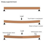 |
The graphic on the left shows a loaded beam and the
stresses which are produced by bending. As the beam bends the top of the
beam becomes slightly shorter and the bottom of the beam slightly
longer. The top of the beam is in compression and the bottom is in
tension; the stresses are greatest at the top and bottom edges, becoming
smaller and smaller as the middle of the beam is approached. Along the
neutral axis, which runs horizontally along the centre line of the beam,
there is neither compression nor tension. Vertical shear stress occurs due to the tendency of the beam to shear under load, particularly near each supported end. Horizontal shear stress is caused by the fibres trying to slide over each other as the top of the beam is shortened and the bottom lengthened. |
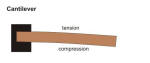 |
A cantilevered beam behaves in the opposite way. The top of the beam goes into tension and the bottom compression. |
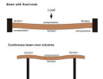 |
If a beam is supported at both ends and the ends are rigidly fixed
the behaviour of the beam is a bit more complex. The beam is less
inclined to bend than a beam with 'free' ends and, consequently, a beam
does not have to be so deep. In practice, however, it's not easy to
rigidly fix ends. Building a beam into a wall or simply bolting it to a
column usually gives a partial fixing.
If a beam is rigidly fixed to a column (sometimes called a continuous
connection) the saving in beam cost may be offset by the need for a
stronger column - because some of the beam's 'bending' is transferred
into the column. A 'bending moment' is an example
of an internal force ('shear' mentioned above is another one) that is
induced in a structure when loads are applied to that structure.
If a beam runs across the top of a column the top of the beam (i.e. the bit over the column) goes into tension - see left-hand graphic. |
| The early engineers learnt to cope with these stresses in various ways - some solutions were more successful than others. But first they had to understand the materials they were working with; the following sections explain the manufacture and use of cast iron, wrought iron and steel. Although engineers were quite innovative in some respects, i.e. the development of fireproof floors, in others they were quite conservative: for example traditional loadbearing masonry remained the norm for external walls until the early part of the 20th century. The 'pages' explain the manufacture and use of cast iron, wrought iron and steel. Other sections in this topic describe their evolution during the 19th and early 20th centuries. | |
| In the 1700s the production of iron was mostly restricted to the small-scale smelting of iron ores. Iron was produced by smelting it with charcoal but this was in short supply (it was made by partially burning wood to give a carbon-rich material). Coal, a much more plentiful material than carbon, unfortunately produced iron of poor quality due to the high concentration of sulfur. We can thank the Darby family for the development of cast iron as an engineering material because they realised that coal could be used to produce coke (made by heating coal much in the same way that charcoal is made from wood) and that coke was the key to successful iron production. | ||
 |
Iron is extracted from naturally occurring ore - most commonly iron oxide (FeO). In the early days of the Industrial Revolution the production of iron required three stages:
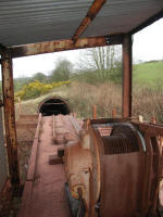
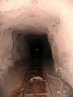
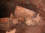
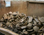
The pictures (left, right and below) show Florence mine on the western fringes of the Lake District. Metal mining in the west of Cumbria was dominated by the large deposits of high grade hematite iron ore found in the limestone strata. |
 |
 |
During the Industrial Revolution most ores were found in the coal
bearing strata where they naturally occurred along side coal (the fuel)
and limestone (the flux). The main British iron ores were:
|
|
 |
The typical chemical reaction of an iron oxide is FeO + C > Fe + CO: Iron Oxide + Carbon heated along with a blast of air > Iron + Carbon Monoxide (a gas released into the air). This process does not yield pure iron, but an impure product called pig iron - so called because the molten metal from the blast furnace was run into long channels with branches formed in sand, called the 'sow and her pigs'. This pig iron was produced in a variety of grades depending on the heat of the furnace and the nature of the original ore. Despite the flux, many pig irons still contained a number impurities including carbon, silicon, sulfur, phosphorous and manganese. |
|
 |
Cast iron is the material produced by re-melting this
pig iron in a cupola (a small furnace). A small amount of limestone flux
was added - the quality and use of the finished cast iron depended on
the quality of the pig iron. Some of the poorer qualities were only
suitable for crude castings such as sash weights while the better ones
were suitable for the manufacture of engines, columns and girders etc.
In the early days of cast iron production, it was difficult to control the level of carbon and other impurities such as sulfur. This meant that the strength and properties of the material were very much a hit-and-miss affair. Consequently, early cast iron structural elements were often load tested before being used in a building. It was also brittle because of the amount of carbon it contained (about 4%). |
 |
 |
Castings were formed by pouring the molten iron into metal frames or
boxes (a top box and a bottom box) containing sand; an impression of the
casting having been formed in the sand using a wooden pattern. The sand
set quite firm and allowed substantial detail in the mouldings. The
wooden pattern was cut a fraction too large to allow for iron's
shrinkage as it cooled (about 1%). Nowadays these traditional techniques
are still used although a special sand is used which hardens quickly
when injected with carbon dioxide. Click here to see a short video clip of a 'traditional' casting. |
 |
Failure of castings (a not uncommon event) could be caused by:
In fact failure was so common that engineers and designers often included specification clauses in contracts which required extensive testing. The example below was written by the architect Theodore Sington in the 1890s. "All the castings are to be made of re-melted iron of a quality and mixture to be approved by the architect; they are to be finished... with clean even surfaces, free from sand, air holes, and all other imperfections or flaws. ...All the castings must be left in the sand moulds for at least ten hours before being taken up. The contractor must state in his tender the description and proportions of the different kinds of iron he proposes to use in the castings, which in respect of strength must stand the following test: Two bars are to be cast each day on which any of the castings are being run, 3ft. 6in. long, 1in. broad and 2in. deep. Upon due notice being given, the architect will test one of these by placing it edgeways on bearings 3ft. apart and loading the middle of the bar. Should it break with any weight less than 25cwt., all work cast with that metal will be rejected. The other bar is to be marked with the date of the casting and delivered to the architect at the works." |
||
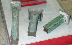 |
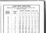
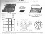
Hollow castings such as columns were carried out in much the same way as described on the previous page but with an inner core of sand forming the 'hollow'. Columns were often cast vertically to help compaction of the metal (this also helped to exclude bubbles etc) and to ensure that the metal was of uniform thickness all round. The image on the left shows some early solid cruciform column castings (c1800). During the 19th century cylindrical columns became the norm and they were usually hollow. As late as the mid 1920s cast iron columns were still readily available. The chart on the right shows the size and load bearing capabilities of a variety of cast iron columns; the table is taken from the Chas Wade catalogue 1926. |
 |
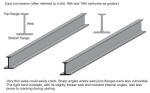 |
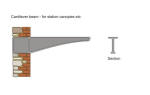
Cast iron has good compressive strength but relatively poor tensile strength. Its average ultimate tensile strength was 9 tons per sq inch and its compression strength 48 tons per sq inch (figures from Rivington's Building Construction 1904). However, producing a good casting was often a bit of a 'hit and miss' affair; as a result big safety factors were adopted. Its safe working strength was generally taken as 1.5 tons sq inch (tension) and 8 tons sq inch (compression). Engineers of the time assumed that the difference in tensile and compressive strength should be reflected in the beam's design. As a result it's quite common to find early beams with small top flanges and wide bottom ones (reversed in cantilever beams - see right). |
 |
 |
In practice the top flange is often quite wide to stop lateral movement of the beam and to provide an adequate fixing for anything on top of it. Engineers also realised that because the stresses from loading were greatest at the centre of the girder, the centre section should be stronger and therefore bigger in cross sectional area than the ends. In practice beams can be found in a variety of shapes and it's not uncommon to find ones which don't conform to some of the principles mentioned above. The beam shown on the left dates from the 1850s. It shows a beam which tapers slightly at each end but with top and bottom flanges pretty similar in size. Note how the beams are joined to the columns; this arrangement, with lugs on the end of the beams bolted around the columns, was fairly common during the 19th century. | |
 |
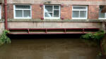
Vertical ribs or 'feathers' were sometimes cast into girders to act as stiffeners. The graphic on the left shows a typical early beam designed to carry a fairly substantial load. The example on the right shows a slightly different design of ribbed cast iron girder carrying part of Masson Mill over the mill race. A number of these girders were used, laid side by side. Some 19th century textbooks suggest that cast iron girders should be limited to a span of about 20 feet (6 metres) and that the depth of the girder should ideally be about 1/12th of the span. |
 |
 |
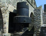
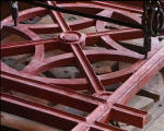
Armley Mill in Leeds is a good example of an early mill which
incorporates cast iron in its structure. There have been mills on this site since the 17th
century,
although the present building dates from 1805. Benjamin Gott, a major
figure in the industrial development of Leeds bought Armley Mill from Thomas Lloyd (a cloth merchant),
but had to rebuild it the following year after it was almost entirely destroyed by fire. Gott re-built the mill
using 'fireproof' materials wherever possible, i.e. brick for the external walls, and iron
and brick for the floors. Gott became one of
the biggest and wealthiest employers in Yorkshire and when he died in 1840 his sons, John
and William, took over the mills and continued to develop the family's
textile interests. It was they who installed a steam engine in 1850. The mill survives largely intact to
this day although cloth manufacture has long since ceased; it's now an industrial museum run by Leeds City Council.
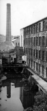
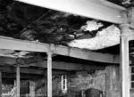
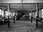
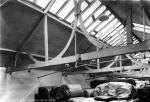
The left-hand picture (all pictures are from the mid 1970s) shows part of the factory and the goit at Armley. The goit (head race) provided a channel directing part of the river over the water wheel; the chimney behind it was not built until the arrival of steam. The top right-hand image shows the interior of the corn mill built in the 1790s at Armley Mills. At this time Armley was noted for its corn as well as its fulling mills. It has cast iron columns and beams - note that the beams are slightly convex (deeper near their mid span) but without a bottom flange.The middle picture shows the fireproof structure of the main block of Armley Mills (picture taken on second floor). This construction is explained in more detail in a later section. The bottom picture shows the cast iron roof trusses of a drying shed; original clips can be seen on the trusses. Cast iron roof trusses are comparatively rare - wood remained the choice of most mill designers for roof structures until quite late in the 19th century when it was replaced by wrought iron and steel - sometimes with cast iron for the compression elements. A later section explains the evolution of iron and steel roofs. |
 |
 |
||
 |
||
 |
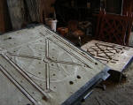
Cast iron was used to make hundreds of products besides columns, beams
and roof trusses. These included, amongst many others, inspection
covers, gratings, lamp posts, windows, guard rails, gates, fences, and
fire escapes. Crystal Palace, designed by Joseph Paxton and Charles Fox, was built to house the Great Exhibition (Hyde Park, London 1851). The structure was based on Paxton's experience designing greenhouses for the Duke of Devonshire and was made from glass, cast iron and wrought iron (see below). Nearly all the components were made in Birmingham and Smethwick. The huge structure was 1848 feet long (approx. 560 metres) and 454 feet wide (approx 135 metres). After the Exhibition the building was taken down and re-erected at Sydenham, south London, an area that became known as Crystal Palace. It was destroyed in a fire in 1936. |
 |
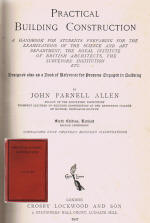
| Wrought iron (rolled iron) became more readily available during the middle of the 19th century. Although its compression strength was slightly less than cast iron, its tensile strength was considerably higher. It was also more predictable and less brittle than cast iron so less likely to crack and cause catastrophic failure (in old buildings still in use today a common cause of partial collapse is fracture of cast iron columns caused by impact damage - usually fork lift trucks). Initially wrought was much more expensive than cast iron due to its lengthy production process. Designers soon realised its potential for beams although columns were still usually formed in cast iron until the early 20th century when they were superseded by steel. Despite wrought iron's advantages many mill designers were slow to exploit its potential and, so, in the latter part of the 19th century cast iron beams were still widely used. However, the designers of other structures were more adventurous and wrought iron became common in bridges, wide span roofs (i.e. stations) warehouses and offices. Its manufacture is described below - the paragraphs have been taken from Practical Building Construction by JP Allen, published by Crosby Lockwood in 1927. | ||
 |
"Wrought Iron, which has now, to a great extent, superseded cast-iron, except
for ornamental purposes, is the product of 'Forge Pig', the resulting metal
containing not more than 0.15 per cent of carbon. The excess of carbon, it is
obvious, must be extracted from the iron, the usual processes being as follows:
The pig iron is first puddled or melted clear of any fuel, but with other substances (containing oxygen) to take out the remaining carbon; and when this is done the metal is collected and cooled into lumps, which are then shingled or placed under a heavy hammer, by which the iron is consolidated, and any other foreign matters are crushed out. The bloom, as it is called, resulting from this hammering, is then rolled (left), while still hot, into puddled bars, which are the first and lowest quality of wrought-iron. As manipulation improves the tenacity and strength of wrought-iron, these puddled bars are cut up, piled, heated, and rolled as before; forming the merchant bar, or second quality of wrought-iron; and a repetition of this process produces the best bar, B, or third quality; while Best-Best, B B, and Best-Best-Best, B B B are the outcome of further repetitions - each such operation having the effect of giving the iron a more uniform fibrous nature. |
|
 |
Good wrought-iron is of a very tough, fibrous, and weldable nature. It should be capable of bearing 24 tons per square inch, ultimate tensile strain, and about 20 tons of compression and shearing; equivalent to safe loads of about 5 and 4 tons respectively. These two powers of resistance are so much more nearly equal in wrought than in cast-iron, that top and bottom flanges of a girder may be made alike, with little waste of material or forfeiture of strength. Therefore girders or joists could be rolled to sections and, in addition, they could be built up to any size, section, or design; because the wrought-iron could be welded, riveted, bent, rolled, or otherwise worked to any form, which cannot be done with cast iron on account of its brittleness. The surface of the fracture of good wrought-iron, under a weight applied slowly and gradually, should be stringy in appearance, as if every little fibre had held out to the last on its own account, some with greater success than others; while the fracture under a sudden shock would be of a more crystalline nature, its coarseness or fineness indicating its quality; the same deductions being drawn from the fine or coarse strings of a gradual fracture." |
|
 |
Initially the small amounts of wrought iron that could be made in one go, and the limitations of rolling machinery, meant that there were practical limits on the cross sectional size of girders - substantial ones were therefore usually plated (built up from smaller sections using plates, tees, angles, bars etc). Plating also enabled strength to be added to those parts of a girder under most stress. The next page shows some examples of plated girders. 'I' beams, so called because of their shape (see right-hand graphic), were initially only available in limited sizes. |
 |
 |
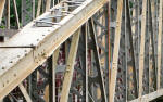
Jubilee Bridge (1887) crosses the River Derwent at Matlock Bath
in Derbyshire. It's a good example of a structure made from different
wrought iron sections riveted together. The bridge cost £230 and spans 85 feet, about 26 metres.
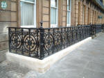
Wrought iron was also used for decorative work. This included ornamental scroll and repousse work on hinges, screens, gates and balustrades. As iron production improved, smiths could depend on reliable supplies of iron in standard measurements, and so could devote their energy to ever more elaborate designs. |
 |
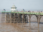 |
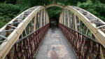
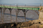
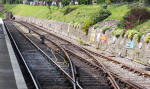
Many structures exploited the unique characteristics of both wrought and cast iron. For example, many seaside piers were built on a framework which comprised a series of cast iron columns braced with wrought iron stays. At Clevedon in Somerset the pier supports originally consisted of eight 100 ft arched spans leading to a landing stage. The exceptionally slender spans are constructed from surplus riveted broad-gauge railway track (wrought iron) designed for the Great Western Railway. Part of the pier collapsed in 1970 (ironically under load testing). Since then it has been restored and is now a Grade 1 listed structure. |
 |
| Wrought iron (for structural work) was slowly superseded by steel in the latter part of the 19th century. Note - more information on the conservation of cast iron and wrought iron can be found in the Iron topic (from Home Page). | ||
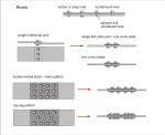 |
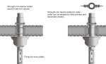
Most wrought iron work was joined by riveting. This gave a much stronger and more reliable joint than bolting. In the mid 19th century riveting was usually carried out by hand although by the end of the century hydraulic and pneumatic riveters were available - the latter gave a better and more consistent joint. The rivet was heated until red hot and then hammered close to the face of the plate. As the rivet cooled it contracted and drew together the face of the plates. Rivets were made from good quality wrought iron (steel work later in the century was also riveted - but with steel rivets). The pitch of the rivets (centres) was typically 3" to 5" (75 to 125mm) and the shank diameter was typically 1" if joining ½" plates. (wider for thicker plates). The holes (slightly larger than the cold rivet) in the plates were punched or drilled. Joints were lapped or 'fished' with cover plates. | |
 |
When wrought iron first became relatively common (mid 19th century) there were limits on the sizes of beams that could be successfully rolled. To get over this problem beams were made from angle sections and flat plates riveted together. They could also be made by 'compounding' smaller beams. This in fact offered a number of advantages - the components could be more readily transported to site and, as Rivington stated in his 'Building Construction' (originally published in 1875); ..."the number and thickness of the plates used in a built-up girder may be varied at different parts of it, in proportion to the stresses which come upon those parts; whereas in a rolled girder, the thickness of the web and of the flanges is necessarily unvarying throughout, and if, therefore, these are thick enough to withstand the greater stresses, they are too thick in those portions where the smaller stresses occur." | |
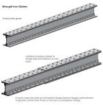 |
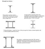
A simple rolled wrought iron 'I' beam or a simple plated girder was
generally assumed to have a span capability of about 20 times its depth.
For greater spans or where loads were expected to be particularly high
the flanges could be reinforced by adding extra plates top and bottom.
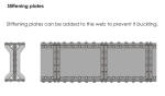
If the beams had a deep web (i.e. large compound beams designed to cope with very high loads) there was the danger that the web could buckle under load. This was resisted by reinforcing the web with stiffeners, usually 'T' sections riveted to both sides of the web. |
 |
 |
Wrought iron was much more expensive to produce than cast iron and, in fact, not as strong in compression. The manufacture of cast iron columns, therefore, continued well into the 20th century. A wrought iron beam could be connected to a cast iron column in a number of ways - two are shown in the left-hand graphic (neither of them use rigid fixings as described in the first page of this section). Wrought iron beams, despite their many advantages were not common in textile mills. In fact, many mill designers 'by-passed' wrought iron, making the jump from cast iron to steel beams towards the end of the 19th century. | |
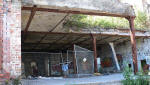 |
Although many mill designers were slow in exploiting the capabilities of wrought iron others were quick to spot its potential. The building shown here (Bristol), originally a soap works built in 1865, has been in a partly demolished state for several years. The partial demolition has exposed an interesting floor structure. This comprises wrought iron plated girders with a brick arch infill supported by the external loadbearing walls and, internally, by cast iron columns. Note that the top and bottom flanges of the girder (look at the one in the background - left-hand picture) are not parallel. |
 |
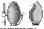 |
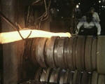
The production of 'wrought' iron was a slow, small-scale, labour intensive and expensive process. Fortunately, scientists and engineers were gaining a growing understanding of the role of carbon in iron's metallurgy. Cast iron is brittle because of its high carbon content (about 4%). Wrought iron, by comparison, contains less than 0.2%. Steel is an alloy iron that contains about 0.4%. In the Bessemer process compressed air is blown into the bottom of the converter (see left) which contained molten pig iron. During this process excess carbon in the iron burns and the other impurities form a waste slag. The converter can be tilted to empty the newly formed steel. | |
 |
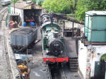
The Bessemer process was patented in 1855 although the technical problems of producing good quality steel from alkaline ores, coupled with the conservative nature of many building designers, meant that wrought and cast iron were still specified in many buildings. The technical problems, mostly caused by phosphorous, were resolved by the early 1880s. In fact, between 1870 to 1905 there was a tenfold increase in steel production. During this period the production of wrought iron and cast iron fell by nearly two thirds. Steel was cheaper to produce than wrought iron and had better tensile and compressive strength. This strength, i.e. its safe working load, was eventually established at 7.5 tons per sq inch in both tension and compression (increased during the Second World war for certain types of building). Steel was also ductile, fatigue resistant and it was easy to weld and rivet. However, it was the railway industry, not the textile industry, which was responsible for the initial growth in steel production: from the early 1860s steel was used for rails (left), and from the early 1870s, wheels, axles and boilers. |
 |
 |
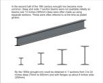
The use of steel for structural frames developed slowly. In the
late Victorian period rolling processes improved and steel became
available in a variety of cross sections; common early ones were the
'I' section, the angle and the tee. Like wrought iron, steel girders
were often plated, i.e. made up from several riveted sections. Early
'I' section beams had to be rolled with tapered flanges: not until
1959 did Dorman Long introduce the rolling of sections with parallel
flanges and sharp corners. Parallel flanges had two big advantages:
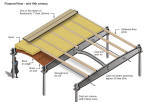
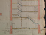
By the early 1900s steel was commonly used (in the form of rolled steel joists) for floor structures although the beams themselves were usually supported by cast iron columns or traditional load bearing walls. The drawing on the left (1904) shows a cross section through a proposed warehouse - another section in this topic describes this building in more detail. |
|
 |
There are various claims for the first steel framed building in
the UK. The claims are difficult to substantiate because the terms
'iron' and 'steel' were often used carelessly (by writers and
reporters - not engineers). In addition some early, so-called,
framed buildings often had loadbearing external walls (as shown
above) or a series of columns supporting the floor structures but these columns were
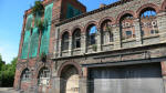
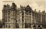
located against self-supporting external walls. The first UK building to make extensive use of steel was probably the National Liberal Club in London built in 1879. This building incorporated built-up columns and girders of steel (and some of iron) with steel columns set back from the self supporting external walls. The first fully steel framed building in the UK was probably the Royal Insurance Building, Liverpool (1895-6). It has 7 floors plus two basement levels. The frame is clearly evident from within the building and the original drawings show that the framing is complete. In 1900 the Midland Hotel in Manchester was built (left) with a six storey steel frame. |
|
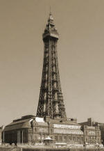 |
Perhaps the earliest and most dramatic steel structure in the UK was Blackpool tower. This was an imitation of the Eiffel Tower (built a few years earlier in wrought iron). The English Heritage listing describes it as: "...Tower of open steel girders. Square plan; four concrete foundation blocks 35 feet square and 12 feet thick with rolled steel joists and steel bedplates support four square-braced stanchions, each consisting of four pillars braced together with lattice girders, tapering in the height from 100 feet width at base to 30 feet width under main gallery, which is enclosed in glass, with three open galleries above. Ogee shaped cap, topped with flag mast terminating 518 feet above ground..." The tower contains nearly 2,500 tons of steel and 93 tons of cast iron. In a 70mph wind the tower sways by 1 inch (25mm). No one can feel this because the tower is usually closed if winds exceed 45mph. The tower is re-painted every 7 years (and, apparently, it takes 7 years to paint it.) |
|
©2008 University of the West of England, Bristol
except where acknowledged