![]()
1 Foundations
2 External walls
3 Ground Floors
4 Upper Floors
5 Roof Structure
6 Windows
In 1875, the Public Health Act was introduced. It required urban authorities to make byelaws for new streets, to ensure structural stability of houses and prevent fires, and to provide for the drainage of buildings and the provision of air space around buildings. Three years later the Building Act of 1878 provided more detail with regard to house foundations and wall types. The Local Government Board, itself established in 1871, issued the first Model Bye-laws in 1877/78 ('by' or 'bye' is old Danish and means local). With regard to foundations, the bye-laws stated that walls should have stepped footings (twice the width of the wall) and implied that concrete (9" thick - 225mm) should be placed under the footings unless the sub-soil be gravel or rock ('solid ground'). Text books of the time suggested that Portland cement made the best concrete although hydraulic lime was the next best thing. Common lime (hydrated lime) was seen as a much inferior product. A mix of approximately of 1:1:4 or 1:1.5:5 was recommended, cement:sand:stone. It is not clear how many local authorities adopted these bye-laws outside London; many produced their own - often less onerous than the Model ones.
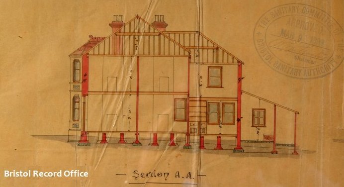
The drawing below shows a section of a proposed house (Bristol 1898). You an see the main walls have brick footings with concrete below.
The London County Council was created in 1889, and sponsored the London Building Act of 1894 which amended the rules relating to foundations and the thickness of external and party walls. This seems like a backward step - they no longer mention concrete footings, instead relying just on brick ones. A writer at the time noted, "the bye-law on the whole is a wise one, as concrete is so easily scamped, but there are many cases in which concrete alone would be more economical and more stable".
Part of the requirements for external walls and footings from The London Building Act 1984 is shown below. By today's standards the foundations seem very shallow; in fact many text books from the time suggest that foundations should never be less than 12 inches (300mm) deep and often much more. These standards were generally higher than those adopted by provincial towns and cities.
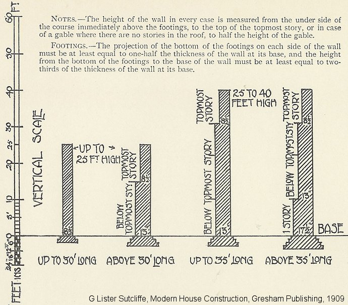
Many local authorities were slow in adopting Model Bye-laws; even where they did, building control was fairly lax. This meant that the nature and quality of foundations varied considerably. The graphics below show typical foundations at the end of the 1800s. The depths varied according to circumstances but generally they were shallower than their modern counterparts.

The drawing below dates from 1903 and shows a section through a planned house. The foundations look quite shallow (and there are no brick footings). Whether or not this was just a drawing convention of the time we do not know; presumably the depth of the actual foundation would depend on specific circumstances.

Reinforced foundations were not unknown. G Lister Sutcliffe states, "..frequently the metal is in the form of steel rails....or twisted wires... embedded in the concrete. A stronger foundation can be obtained in less depth than when concrete alone is used".
During the 1920s and 30s foundations remained much the same. Text books from the 1930s suggest that in clay soils foundations should be 3 feet deep (900mm) - guidance in fact not much different from today. London Building Acts and Model Bye-laws introduced a number of minor amendments (see below). The examples below were suitable for houses with foundations in firm clay or coarse sand.
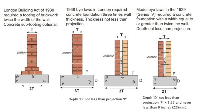
Note that the 1939 bye-laws still permitted brick footings and also mentioned the option of rafts and piles.
The foundation below was built in the early 1930s. It's about 500mm wide, 200mm thick and probably 400mm, or so, deep.
In the late 1940s and throughout the 1950s most new houses were built with strip foundations. Raft foundations were also popular, particularly under system-built properties or over areas of fill. A typical raft comprised a concrete slab 6" to 9" thick (150mm to 225mm), suitably reinforced. A few foundations were piled - short bored piling systems became common during the early 1960s. The piles were typically 6' to 12' long (1.8 to 3.6m), not normally reinforced but with a reinforced ground beam over the top, cast on some form of compressible material (ash or clinker).
The Model Bylaws were replaced by National Building Regulations in 1965. These Regulations were applied generally throughout England and Wales, with the exception of the Inner London Boroughs (the area of the former London County Council) where the London Building Acts continued to prevail. Various amendments and revisions to these Building Regulations were issued increasing the scope and areas covered by Building Regulations. This continued until the Building Act 1984 finally consolidated Building Regulations under one piece of legislation. This resulted in the introduction of the Building Regulations 1985 that came into operation in November 1985.
The Building Regulations contain 'deemed to satisfy' provisions for strip foundations. For modest loads and on certain types of ground acceptable strip foundation widths are given - see the Building Regulation section for the table itself. Outside these boundaries, for example a 4 storey building on soft clay, the foundation has to be specifically designed.
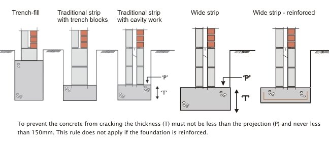
Raft foundations and piled foundations do not have any 'deemed to satisfy provisions' and always need to be designed. Today, rafts are comparatively rare except in former mining areas. Piling has become very common for four main reasons; it's much cheaper than it used to be, smaller, lighter piling rigs are now available, shoring traditional trenches is expensive, and brownfield sites are often not suitable for strip foundations.
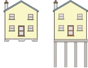
There is much more information on piling in the Foundations section of this web site.
During the 1700s there were a number of improvements in brick making. Blended clays, better moulding techniques and more even firing gave greater consistency in brick shape and size. Fashion dictated brick colour: the reds and purples popular in the late 1600s gave way to softer brown colours in the 1730s. By 1800 the production of yellow London stocks provided a brick colour not that much different from natural stone. The repeal of the brick tax in 1850 gave the brick industry a new impetus. Improved mixing and moulding machines, together with better firing techniques, allowed brick production to reach new heights. Bricks were now available in a range of colours, shapes and strengths that would have been unimaginable a 100 years earlier. Better quarrying techniques allowed extraction of the deeper clays which produce very strong, dense bricks; vital for civil engineering works such as canals, viaducts sewers and bridges.
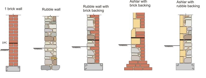
By the end of the 19th century most houses had walls of at least one-brick thickness. Houses over three storeys often had thicker walls, usually reducing in thickness at each upper-floor level. The brickwork itself (at least the brickwork on view) was generally laid to a very high standard. Most houses were built in Flemish bond although rear walls or walls hidden by render were often laid in Garden wall bond (usually English).
Stone was often used for prestigious buildings or in areas where it naturally occurred. In upland areas (the north and west) stone was often the obvious choice for building because it was readily available (and prior to the railways these were often areas where bricks were expensive). There are 3 groups of stone; igneous, sedimentary and metamorphic. The sedimentary group, which includes limestone and sandstone, accounts for most of the stone used for building in the UK.
Rubble walling is found in a variety of styles. At its cheapest it comprises rough stonework, built as two outer leaves and bound together with copious amounts of lime mortar. More expensive work comprised squared rubble possibly set against a brick backing. In most situations a stone wall has to be thicker than a brick one. So, whereas a 1 brick thick wall (215mm or so) might be fine for a two or three storey house, a stone wall is likely to be 325mm or even more. Most rubble walls were pointed flush or slightly recessed. The ribbon pointing so often seen nowadays is not traditional, neither is it particularly durable.
Stonework which is dressed and/or finely cut is often referred to as dimensioned stone. Sometimes it's referred to as freestone. This means it can be worked (cut, shaped and smoothed) with a chisel and a saw in any direction. It has a fine grain and is free from obvious laminations and pronounced bedding planes. In the 18th century whole cities were built (some rebuilt) in stone. It was not cost effective to build the whole of the wall in freestone and a backing material of rubble or brickwork can nearly always be found. In some houses only the front elevation would be built in freestone, the sides and back being constructed of rubble or brick. To bond the two halves of the wall together, 'through' or bonding stones were used.
Where the freestone is laid with very fine joints, almost invisible from more than few feet away, the work is knows as ashlar. In some parts of the country the stones were cut with a taper to make the joints easier to form. Wedges made from bits of timber or even oyster shells were often pushed into the back to provide stability as the mortar set. These buildings were built with lime mortar which hardened very slowly. Hydraulic limes were not unknown but they were less common and more expensive. In addition they often set too quickly resulting in high waste on site.
Lime mortars were common until the 1930s, in some parts of the UK, even later. Limestone or chalk was burnt with coal to form Quicklime. The burnt lime is known as lump lime. The Quicklime was then slaked with water and then mixed with fine aggregates (nowadays sand) to form mortar. It could take many months for a lime plaster to fully set. Then process is known as carbonation. Some limes have a hydraulic set (a bit like a weak cement). This could be induced by adding pozzolans which contain silica. Another option was to use a lime which naturally contains silicas (usually a proportion of clay). A hydraulic 'set' is quicker and stronger than carbonation. Some of the very strong hydraulic limes are not dissimilar to modern cement; made of course, from chalk and clay.
During the 1930s and 1940s cement mortars gradually replaced lime ones. Lime
was often added to the mix to improve its working and qualities and durability.
More detail can be found lower down the page.
In the early 1900s period joints were usually finished flush or slightly
recessed. Where very good quality bricks were used the joints were often
only 8mm, or even less. This, together with the use of brick dust in the mortar,
meant that the mortar had very little affect on a building’s appearance.
Working-class housing was usually pointed in a lime mortar which included
local industrial waste products as fine aggregate. Perhaps ash was the most
common. The photos below show three examples of good quality 19th century brickwork.
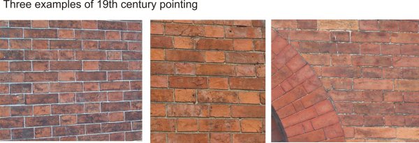
Tuck pointing was usually reserved for the best quality work. Tuck pointing is basically in two parts, a bedding mortar often containing aggregates to match the colour of the bricks or stonework, and a thin ribbon of lime pointing to finish the joint. From a distance a wall that is tuck pointed appears to be finely jointed. Examples of tuck pointing can be found under the Walls section of this web site.
In the latter part of the 19th century a number of houses were built with
cavity walls. It was not, however, until the 1920s that this became the accepted
form of construction. Cavity walls were cheaper to build than their solid wall
counterparts. In addition they offer improved thermal insulation and better
weather protection. Most walls comprised two half-brick leaves with a 50mm
cavity. The two halves of the wall were tied at regular intervals with steel or
wrought iron wall ties. The external leaf of brickwork was laid in facing bricks, the internal
leaf in commons. A few early cavity walls had an external leaf one brick thick
and, in some early forms of construction, the DPC ran right across the cavity.
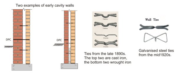
DPCs (to prevent rising damp) were in common use by the early 1900s. They could be made from lead, pitch, asphalt and slate. Not until the mid 1920s did vertical DPCs become a standard detail around openings.
During this period cavity walls changed little. Mortars gradually became cement-based rather than lime-based because the faster setting mortar meant faster construction. Blockwork became a common material for the inner leaf of cavity walls - the blocks were usually made with an aggregate of stone or industrial waste (clinker and breeze were common). A few houses, usually Modernist-style houses with a rendered finish, were built with walls of solid blockwork (i.e. non cavity).
Note that during the 1950s and early 1960s several thousand houses were built in non-traditional construction. These were often constructed using precast frames or panels; in some cases insitu panels. Some systems were based on timber. For more information go to the System Building section of the web site.
In the 1970s insulation standards slowly improved. A maximum 'U' value of 1.70 was introduced in 1972 (a measure of a the wall’s ability to transmit heat - explained further in the Walls section). Achieving this standard was relatively easy; a brick external leaf, a 50mm cavity, and a dense block inner leaf finished with 13mm lightweight plaster, just made the 1.7 threshold. In 1980 the maximum U value dropped to 1; this required lightweight blockwork in the inner leaf. From this period to the present day most lightweight blocks have been made from aerated concrete. They were (and still are) made from cement, lime, sand, pulverised fuel ash and aluminium powder. Once these materials are mixed with hot water the aluminium powder reacts with the lime to form millions of tiny pockets of hydrogen. However, there are several other materials for blockwork which have enjoyed brief popularity. These include concrete blocks faced with insulation, hollow blocks containing polystyrene granules and blocks made from pumice or no-fines concrete.
In the 1990s the maximum U value dropped to 0.45; this normally required a very thick lightweight inner leaf or cavity insulation. There are three common options, most of which require lightweight or aerated blocks in the inner leaf. These are:
It is still possible to build solid walls - but this is impractical using brick. Only aerated concrete will give acceptable levels of insulation.

At the time of writing (2006), U values have to less than 0.3 so a modern cavity wall has a ‘U’ value some 5 or 6 times better than its 1920s counterpart. In the above examples slightly thicker insulation will give a U value of 0.30. In modern construction cavity widths have increased well beyond the 50mm common 80 years ago. A 50mm clear gap is required if board insulation is used. This commonly requires a cavity 90mm wide.
Wall ties are now mostly stainless steel. There are various patterns; the washer shown below is to hold insulation boards in position against the inner leaf. These particular ties are all made by Ancon.

Modern mortars are made from cement and sand. Hydrated lime (i.e. bagged
lime) is often introduced into the mix to give it a more plastic feel and to
make it more ‘workable’. Lime also improves the mortar’s ability to cope
with thermal and moisture movement. In recent years the use of pre-mixed mortars has become common. These are
delivered to site in sealed containers, ready for use. They usually contain a retarder so they remain usable for 36 - 48 hours or so. At the end of this
period they develop their strength in the same way as normal mortars.
The face of the joint may be finished in a number of ways – the three most common are shown below. Tooled joints
(where the mortar is pressed against the brickwork) offer the best weather
protection because the tooling smoothes and compresses the joint.

This is a copy of an older 'hand out' on evolution - you may find it useful.The images are pre-publication proofs from 'House Inspector'.
Most houses at the end of the Victorian period (1900) were built with suspended ground floors. There were exceptions to this. Many houses had ground floors constructed with stone or clay flags; basements too were covered with flags. These were laid on a bed of ashes or directly onto compacted earth. Houses without basements usually had a scullery at the back of the house, often in a rear extension. Most sculleries had solid floors - they were used for washing and were likely to stay wet for long periods. The scullery floor was often 6 inches or so (150mm) below the main house floor in case of leaks or flooding. Some of these solid floors were made from concrete.
A typical suspended timber floor from about 1900 comprises a series of joists supported by external and internal loadbearing walls and covered with floorboards. Deep joists were expensive (they still are) and to reduce joist size there were usually intermediate supports known as sleeper walls. These are small walls in rough stone or brickwork built directly on the ground or on small foundations. In practice, ground-floor joists are often half the depth of those used in upper floors where, of course, such intermediate support is not possible.
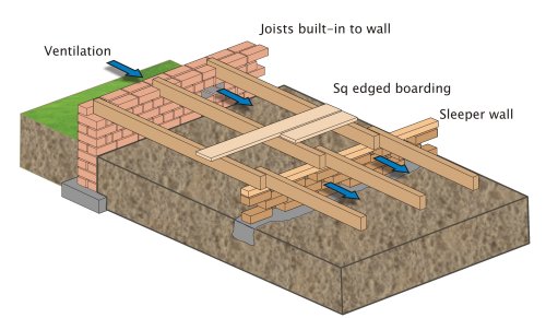
The joists are typically 100mm x 50mm and are usually at 400mm centres or so (16inches). To ventilate the sub-floor void terra cotta or cast iron air bricks were built-in to the external walls. In practice ventilation was not always effective, partly because there were not enough vents and partly because these houses were terraced. This meant that there were only two external walls. In addition, the sleeper walls were not always honeycombed (i.e. with ventilation gaps); this impeded cross ventilation.
Towards end of the Victorian period DPCs, often formed in brittle materials such as slate, were becoming common (but by no means universal). These helped protect the joist ends from rising damp.
 In practice such floors often give rise to expensive
maintenance problems due to poor design and varying standards of workmanship.
They were generally badly ventilated, often prone to flooding (the ground level
under the floor was often lower than the ground outside), and the joist
ends are always at risk because they are normally only protected by a
half-brick thickness of wall.
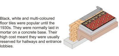
Some houses had concrete floors in the hallways, or maybe just in the lobby by the front door. These were usually covered with decorative tiles laid in mortar on a concrete slab (left).
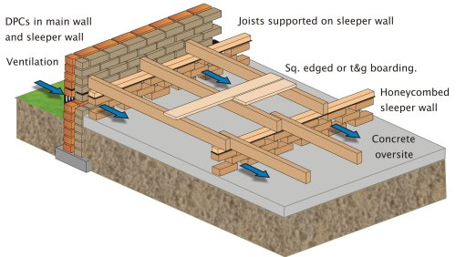
During the first 20 years of the century suspended timber floors changed. A number of improvements were introduced, mostly damp related. In the graphic below note that the entire floor is separated from the substructure by the DPCs. In addition, the bare earth is covered with a concrete slab (often referred to as an ‘oversite’) which is at, or above, external ground level to prevent the build up of water. The slab also prevents growth of vegetation. The floor joists are supported by honeycombed sleeper walls, through which air can pass easily, and the joists do not touch the external wall. Because most of these houses were detached or semi-detached, rather than terraced, the underfloor void is relatively easy to ventilate.
Concrete ground floors were not unknown in the 1930s but they became more common in the 1950s because of the post War restrictions on imported timber (restrictions lasted for nearly 10 years). The floor is basically a bed of concrete, supported by the ground directly beneath it, and quite independent of the surrounding walls.
A typical floor from the 1950s might comprise a layer of hardcore (stone or broken brick), a concrete slab probably 100 to 125mm thick and the floor finish. This is often timber to disguise the nature of the floor, or, in cheaper construction, thermoplastic tiles laid in bitumen adhesive. Some floors, by no means all, contained damp proof membranes, usually liquid based.
In many houses the only barrier to rising damp was the bitumen bedding material under the wood blocks or thermoplastic tiles. Thermoplastic tiles were first produced in the UK just after the Second World War. The tiles were made from a mixture of resin binders, mineral fillers, asbestos and pigments. Most were 9 inches square (225mm). Early tiles were quite brittle. Asbestos vinyl tiles were introduced in the mid 1950s; they were made in much the same way but they were more flexible.

From the mid 1960s to the mid 1990s a typical concrete floor comprised a layer of hardcore, a polythene damp proof membrane laid on a thin bed of sand (to prevent puncturing), and a floor screed.

Hardcores varied in quality - many have since proved to be totally unsuitable. In the mid 1960s polythene damp proof membranes were introduced and became an accepted form of damp proofing. This barrier was usually laid below the concrete slab. DPMs on top of the slab, i.e. sandwiched under the screed, were also common and usually in liquid form, e.g. hot bitumen, or cold bitumen in solution. Liquid DPMs gave the best protection but were more expensive. The concrete slab was usually 100 to 125mm thick. In certain situations, i.e. where the ground was uneven or where there were soft spots below the slab, it might be reinforced with a mesh.
The floor screed provided a smooth finish suitable for carpets or tiling. It was laid towards the completion of the building prior to hanging the doors and fixing the skirtings. It was (and is) is a mixture of cement and course sand (typically one part cement to three or four parts sand) mixed with the minimum amount of water and laid to a thickness of 38-50mm. A few floors had a DPM formed in 20mm asphalt. This could be trowelled to a level finish and precluded the need for a separate screed.
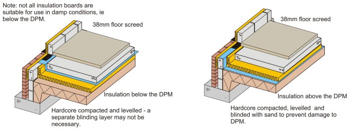
Since the mid 1990s the Building Regulations have required insulation in ground floors. A variety of manufacturers produce a range of rigid insulation boards which can be laid above or below the slab. Some of the boards have a closed-cell structure and are impervious to both water and vapour. They can therefore be laid under the DPM (the DPM is still necessary to prevent moisture rising between the board joints and penetrating the slab). Where boards are laid under the DPM blinding is not always necessary. Typical construction is shown below.
In modern construction chipboard floating floors have become a common alternative to a sand/cement screed. Chipboard and strand board are both very sensitive to moisture and a vapour control layer is normally required under the boarding to prevent drying construction water (i.e. in the concrete) affecting the floor. This membrane is in addition to the DPM below the slab. The tongued & grooved boarding has glued joints and normally sits on a resilient layer of insulation; a perimeter gap of 10mm or so allows for moisture and thermal expansion. This gap is covered by the skirting.
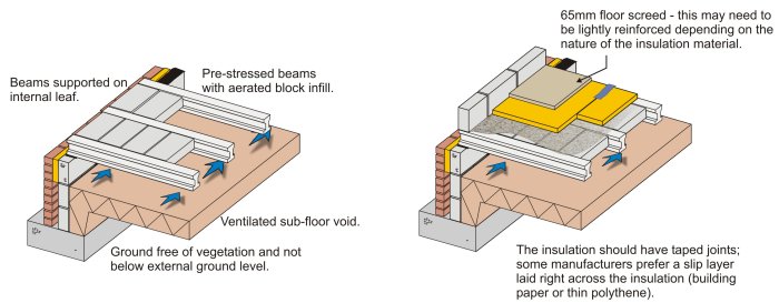
In certain conditions the use of a ground bearing slab is not suitable. In these situations it is common to find a suspended concrete floor. In fact, nowadays, many developers prefer to use suspended concrete floors in all situations because of the perceived risks of ground bearing floors. Until the 1970s these floors were often constructed from insitu concrete but they were slow to construct and very expensive. Nowadays, the floors are usually made from a series of inverted ‘T’ beams, 150-200mm thick, with a concrete block infill. The two most popular finishes are screed or particle board, both laid on insulation.
Nowadays the Building regulations require that the underfloor space is vented; before 2004 it was only necessary to ventilate the space if the ground was not well drained or if there was a risk of gas build-up. DPMs are not required as long as minimum recommended gaps between floor soffits and sub-soil are maintained.
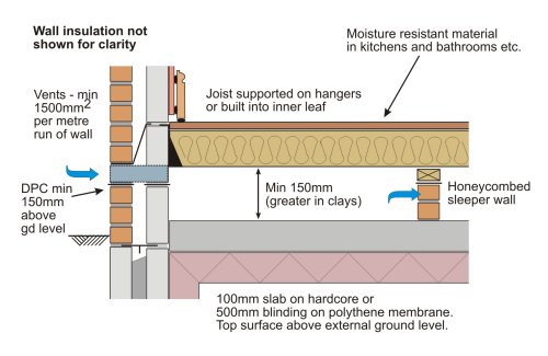
In modern construction timber floors are, once again, becoming popular. The construction is similar to that of 70 years ago although there are a few differences:
This is a copy of an older 'hand out' on evolution - you may find it useful. It includes two pages on upper floors. The images are pre-publication proofs from 'House Inspector'.
The upper floor of a modern house is not that much different from its 1800 counterpart. In other words it comprises a series of timber joists (there are modern alternatives) covered with some form of floor boarding. Nowadays we always expect to find a ceiling although, 150 years ago, the joist soffit was often left open in working-class housing. In modern construction the size and spacing of the joists are subject to the Building Regulations. Before 1965 they were mostly controlled by Model Bye-Laws or accepted building practice.
Note that this brief introduction does not include the construction of floors between flats. Information on this can be found under the Floors section of this web site.
At the end of the 19th century a typical well-built terraced house would have an upper floor constructed from 8" by 2" (200 x 50mm) softwood floor joists fixed at 12" to 16" centres (300 to 400)mm. The joists were usually built in to the walls although occasionally wrought iron or brick corbels were used. Corbels were expensive but did ensure that joists on party walls did not penetrate the brickwork (better sound and fire protection) and that joists on external walls were protected by the full thickness of the wall (less chance of rot).

The floor was normally covered with square-edged softwood boards and finished with a lath and plaster ceiling - usually 3 coats of lime plaster. The direction of the joists can either be party wall to party wall, or front to back. The joists were trimmed around fireplaces and stair openings as shown in the graphic. A half-barrel vault supported the hearth. Note that more information on fireplace construction can be found in the Heating section of this web site.
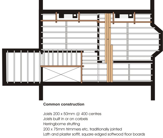
Larger properties may have had double floors, in other words a floor with a primary timber (or steel) beam running at right angles to the joists and supporting them mid span. An advantage of a double floor is that it keeps the floor depth to a minimum and provides all four walls with lateral restraint. Larger, more prestigious, properties sometimes had various types of tongued and grooved boards rather than square edged ones. These are shown further down the page.
In the 1930s the construction was much the same. Contemporary text books show a number of alternative methods of supporting the joists to suit a Model Bye-law of the time which required that no timber could be built within a half brick of the centre of a party wall. The bye-law also specified that all joists should rest upon a wall plate or steel bearing bar (to spread the load across the wall). In practice these bye-laws were often not adopted by local authorities or just ignored. Text books also suggested that joist ends should be tarred or creosoted where they were built into walls.


'Specification' from 1931 provides some general guidance on the construction of upper floors (interestingly enough it does not mention the bye-law requirements). Single floors were normally thought to be acceptable for floor spans up to 16 feet; above that double floors were recommended.
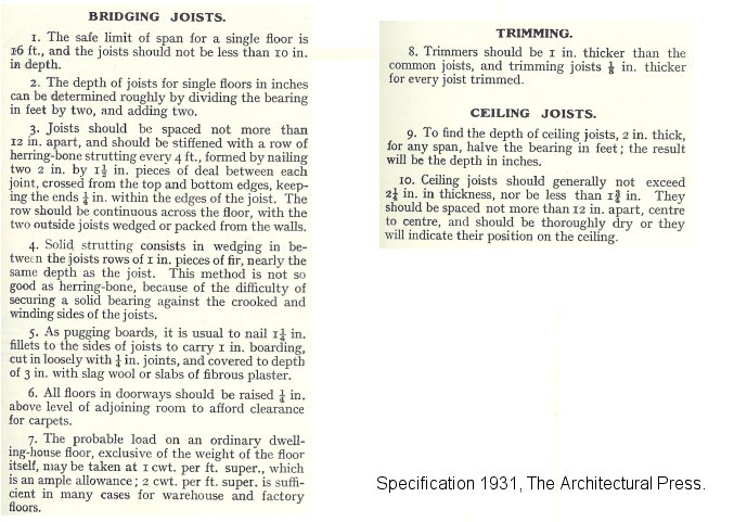
Herringbone strutting was normally recommend at 6 feet intervals (1.8 metres). Unlike Victorian and Edwardian floors the hearth support was often in the form of insitu concrete reinforced with mesh rather than a half barrel vault.

In the post War period timber imports were strictly controlled. Although some system-built houses had floors made from steel joists most houses had fairly traditional upper floors, often with centres 'stretched' and joist sizes reduced, to save timber. In addition strutting was often omitted. Floor coverings were usually tongued and grooved softwood. Boarded ceilings replaced lath and plaster - fibre board, asbestos board and plasterboard (often small sheets - i.e. plasterboard lath) were all common. Joists were built-in or supported on hangers.
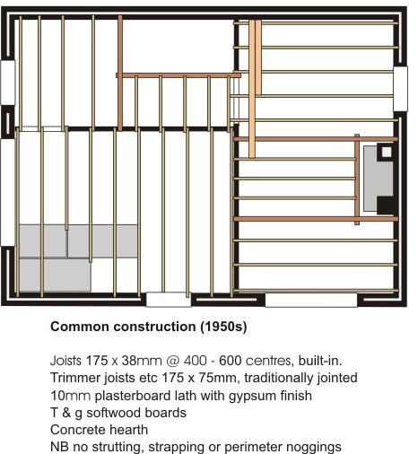
By the 1960s timber rationing was over and floor timbers reverted to pre-War sizes. The 1965 Building Regulations introduced tables for sizing floor joists and these remain much the same to this day. During the 1960s plasterboard became virtually the only material used for ceilings. The boarding was normally 10mm or 12.5mm thick (3/8inch or 1/2inch) with an artex or gypsum plaster finish.
The construction of modern upper floors is shown below. They differ from 1950s floors in three main ways: strapping is now required to restrain the external walls, joist hangers are almost obligatory (to prevent air leakage), and floor boards have largely been replaced by chipboard or strand board. Modern ceilings are still nearly always formed in plasterboard. Nowadays plasterboard lath is rare; the construction usually consists of large sheets of 15mm plasterboard, screwed to joists or to resilient bars, and then taped and painted.
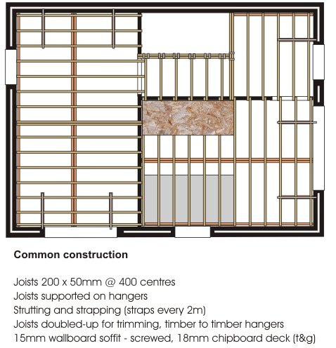
In recent years the use of metal web joists and ‘I’ joists has become more common. In principle these are no different from traditional ‘cut’ joists. One advantage is that they are capable of increased spans. The use of metal web joists also precludes the need for potentially damaging joist notching.

In flats the floors separate dwellings and, therefore, must provide good fire protection and resistance to the passage of impact and airborne sound. The methods of construction shown above are not suitable. Modern options and a brief historical overview can be found in the Floors section of this web site.
During the 19th century the construction of domestic roofs changed little. In the late 1800s timbers were cut by machine rather than by hand, and fixings in the forms of nails, screws and bolts were cheaper and more readily available, but the nature of the structure was much the same as it had been 100 years earlier.
A typical roof comprised a series of sloping timbers known as rafters fixed, at the top to a ridge board, and at the bottom to a wall plate. Ceiling joists supported the ceiling and acted as a tie to the rafters - to stop the rafter feet from spreading. A binder running at right angles to the ceiling joists could be added to help prevent deflection in the joists. In some houses the binder was connected to the ridge by a hanger, again to prevent deflection.
This type of construction could be adapted for larger roofs. The roof shown on the right is the same in principle although there is an additional timber known as a purlin which prevents the rafters from sagging mid span. The purlin is supported by the gable-end walls (party walls in mid-terraced houses) and is sometimes strutted from an internal loadbearing wall (and sometimes the gable walls) to a provide additional support.
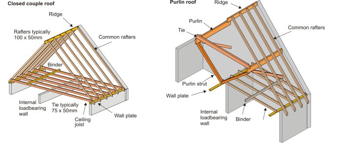
The feet of the rafters were designed to provide a roof overhang or to finish flush with the wall. A fascia board at the feet of the rafters finished off the roof and supported the cast iron or, in a few cases, timber guttering.

Some very large houses with big rooms did not have an internal loadbearing wall in an appropriate position. Other ways had to be found of supporting the purlins mid span. King and Queen post trusses could be used in this instance. These were also widely used in factories and warehouses where large uninterrupted spaces were required.

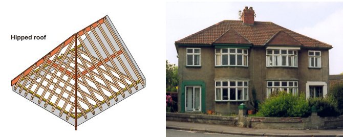
Nearly all the roofs built before 1940 would have been based on the closed couple or purlin design. Sometimes the style was adapted slightly. A hipped roof (below) is a different shape but the arrangement of the timbers is much the same. Larger examples had strutted purlins; larger examples still, had trusses - usually one full truss spanning front to back, and a half truss supporting the end (hip) purlin.
During the War 500,000 homes were damaged or destroyed. In the post War period there was a massive building programme not just to rebuild these damaged homes but also to continue the slum clearance work of the 1930s. But, at the same time, there was a chronic (it lasted for nearly 10 years) shortage of materials. In an attempt to avoid economic disaster the government placed strict limits on the import of materials. Timber was in short supply and new techniques had to be found. At ground floor level timber was saved by building floors in concrete. This was not a practical solution for roofs (apart from a few flat roofs in system-built houses) so techniques were developed which would reduce the amount of timber used in a roof. The TRADA truss is basically a lightweight version of the trusses shown above. They did away with the need for internal loadbearing walls upstairs and allowed for smaller section rafters - often at slightly wider centres. They were common during the 1950s.
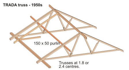
The TRADA truss was
relatively short lived.Most modern roofs are constructed from trussed rafters; they
have been popular since the 1960s. The most common pattern is the Fink or
‘W’ truss designed for symmetrical double-pitch roofs although there are a
variety of shapes suitable for most roof designs. The trussed rafters are
prefabricated and delivered to site ready for lifting onto the supporting
walls, although occasionally you will find the entire roof structure assembled
on the ground and lifted into place by crane.
The timbers, which are typically 80 x 40mm in section, are butt-jointed and held
together by special plates (first introduced to the UK in the mid 1960s) which are pressed into position by machine.
Nowadays the timber are normally pre-treated to guard against rot and insect attack.
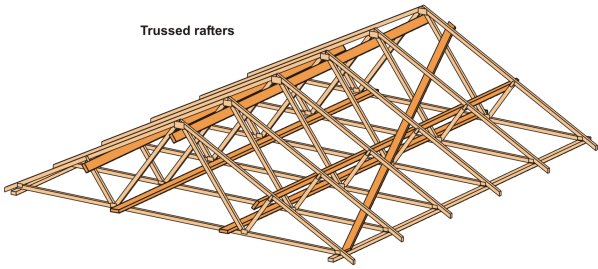
Trussed rafters offer several advantages when compared to traditional roofing methods.
Perhaps their major disadvantage is that use of the roof space for storage (when using normal trusses) is severely limited due to the nature of the timbers. When the trusses are in position additional timbers (braces) need to be added to produce a strong, rigid roof structure. These are explained elsewhere on this web site.
New 'cut' or traditional roofs are sometimes still found but they tend to be one-off dwellings often with living accommodation in the roof space.
Modern trussed rafters and traditional roofs are both supported on softwood wall plates bedded in mortar on the inner leaf of the cavity wall. It's normal practice to strap the roofs to the blockwork inner leaf to prevent them lifting or moving in high winds. Modern roofs are normally ventilated to help minimise condensation. This is usually done by installing air vents at the eaves. There are other methods and these are explained elsewhere on this web site.
This is a copy of an older 'hand out' on evolution
- you may find it useful. The images are pre-publication proofs from 'House Inspector'.
Early windows were usually fixed lights or side-hung casements. All the examples below are mid to late 17th century. The timber window on the far left is part of a timber framed house built in Bristol’s dock area. The second example shows a stone building (c1690) with timber window frames glazed with diamond shaped leaded glass (small panes of glass were much cheaper than large sheets). A hinged, wrought iron casement has been fitted into the right hand section of window. The window on the right has a fixed light directly glazed into the stonework and a hinged iron casement.

In the late 17th century sash windows were introduced to Britain. These windows were usually still formed in small panes because of the limitations of glass technology. The timber sections were quite thick and the window was set flush with the face of the brick or stonework (left hand photo - about 1710). The windows were controlled with lead (later iron) weights which counter-balanced the weight of the sashes. During the Georgian period the glazing bars became thinner and thinner and, at the same time, the windows were set in rebates which hid the box frames. In houses with thick walls the inner reveals often contained shutters (centre photo - about 1800). From the late 18th century onwards it became fashionable (for the wealthy at least) to have full length windows on the first floor leading onto a wrought and cast iron balcony.
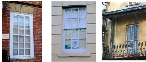
Windows are visually important architectural elements. For example windows were integral to the architectural philosophy of the Georgian era, where their proportions were closely defined in relation to the dictates of symmetry. During the Georgian era window tax was introduced. This was levied on the number of windows in a house and goes some way towards explaining why some windows from this era were blocked up. In the middle of the 19th century this tax was dropped. This change was accompanied by increasing concern with daylight and ventilation, which the Victorians associated with good health. Consequently there was a move towards stipulating minimum window sizes. Towards the end of the Victorian period improvements in glass technology precluded the need for glazing bars altogether.
In the 1920s top hung and side hung casements became popular. The example on the left is from about 1920 and is a crude example of Queen Anne revival sash windows; they were popular during the Edwardian period and were characterised by having a small-paned top sash over a single paned bottom sash - white paint was de rigeur. The right-hand example is from the mid 1930s; casement windows with top hung leaded top-lights (often glazed with stained glass).
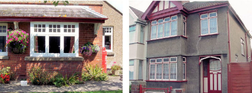
Metal windows, introduced in the very late 19th century, were very common until the 1970s. Early windows were plain mild steel; from the 1930s they were mostly galvanised. As houses became better insulated and less well ventilated their shortcomings became more obvious - the cold inner face of the frames resulted in condensation.
In the post war period high rise housing required new approaches to window styles. Traditional sash windows could not possibly withstand the turbulence and exposure at high levels, and casement windows would be impossible to clean. A common form of window was the horizontal pivot window. These could be made from galvanised metal, timber or aluminium and could be cleaned from the inside.

Aluminium windows (below left) became very popular during the 1970s but, in recent years, have almost completely been eclipsed by plastic. Aluminium windows, like galvanised metal, are good conductors of heat and condensation is always likely to be a problem. In the 1970s a policy of rehabilitating older properties replaced slum clearance and high rise construction. In many cases budgets were not adequate and houses, originally refurbished for 30 years or so, required substantial extra investment after less than 10 years. One example of cost cutting was the louvre window (below right). These were cheap to make, just requiring a simple softwood frame, but were draughty, provided inadequate ventilation in the Summer, and could not readily be used as a means of escape. Other rehab and new houses were fitted with 'standard' timber windows. There were hundreds of styles (below middle). These windows were cheap but mostly made from poor quality timber.

Nowadays, windows are usually made from imported softwoods and hardwoods, or from plastic. There are literally hundreds of styles to choose from. The public has become accustomed to renewing windows, almost as fashion accessories, and often well in advance of their likely life. Because of this, replacement windows has become a very big, but in some cases completely unnecessary, business. The design of windows and the choice of material used may be controlled by planning authorities in conservation areas. Plastic replacement windows are a focus for concern in such areas because they affect character and appearance. Even outside conservation areas the replacement of wooden sash windows will have a significant visual affect on say a street of Victorian terraced houses (below right). The windows on the far right are mock Georgian; the glazing bars are sandwiched between the double glazing.

©2009 University of the West of England, Bristol
except where acknowledged