![]()
1 A Brief History
2 Properties of Cast and Wrought Iron
3 Shaping iron
4 Surveys
5 Ethics
6 Repair techniques - Hot
7 Repair Techniques - Cold
Iron, the fourth most abundant element in the earths crust, occurs widely in
ores with a metal content up to 60%. Iron has a strong affinity for oxygen, but
fortunately carbon has an even stronger attraction for oxygen. At high
temperature carbon will therefore combine with oxygen in the ore, leaving the
metal behind, but much heat energy is required.
Smelting of iron first developed around 2000 BC,--- the Iron Age. By heating iron-ore in the charred embers of a fire blown by bellows, it was discovered that iron ore could be reduced to a spongy metallic bloom and hammered to consolidate and purify it. This was further refined by reheating and hammering, becoming usable worked or wrought iron. The furnace, a bloomery, was a small bowl-shaped hole in the ground lined with clay and blown by manually-powered bellows, achieving temperatures around 700 degrees C. |
||||||||||||
| Wrought iron is too soft to hold a good cutting edge, but around 1400 BC it was discovered that reheating blades in carbon (charcoal) produced a harder and tougher surface that could be sharpened. The carbon combined with the implements surface forming iron carbide, or steel. This steel surface could be heated and quenched in water to produce a hard edge. | ||||||||||||
| Wrought iron production in bloomeries was small-scale and expensive, so in pre-industrial times it was used where its strength, hardness and malleability were essential, eg. in weapons, tools, security applications, (locks, window bars) wearing parts, (hinges, bearings, bell hangers and clappers, parts of machines such as pumps, wind/watermills, etc) fastenings (nails, rivets, collars, cramps,) and ornamentation. Because of its value it was also used as currency and jewellery, currency bars being bent round at their ends to prove that they did not crack, demonstrating their quality as usable iron, and therefore valuable. | ||||||||||||
| Iron-making remained a rural craft until development of the blast furnace probably in the Liege area of Belgium during 14th century. Fed by air-blast from water-powered bellows, temperatures up to 1150 degrees C could be achieved, sufficient to melt the iron, which was cast from the furnace into sand moulds to form finished products, or into blocks (called pigs) for conversion to wrought iron. | ||||||||||||
| At these higher temperatures about 4.25% carbon combined with the iron, making it brittle. Much was therefore refined (in a finery) to produce the purer, softer, forgeable wrought iron which was considered much more useful than brittle cast iron. | ||||||||||||
| Blast furnaces increased the availability of cast and wrought iron, but depended on charcoal as fuel. Shortages of timber and competition from other users made charcoal increasingly scarce in the seventeenth century. Coal could not be used due to the deleterious effect of its impurities on the iron. Then, in 1709 Abraham Darby used coke (purified coal) in his blast furnace at Coalbrookdale, Shropshire. Coke was found to support a larger charge of iron ore/limestone than charcoal did, and allowed blast-air to pass more freely, so blast furnaces could be made bigger and more efficient. | ||||||||||||
| However charcoal was still needed in the fineries to convert pig iron to wrought iron, and shortages continued. (Coal could not be used as its sulphur content caused brittleness in the iron at high temperatures.) | ||||||||||||
| In 1784 Henry Cort developed a furnace at Funtley, Hampshire, where coal was burned separate from the pig iron, its heat being reflected, or reverberated off the roof. The charge was stirred (puddled) until almost all the carbon was burned out by combining with oxygen, then pulled from the furnace, hammered and rolled. After further heating, hammering and rolling it was finally rolled to a wide range of finished sections in grooved rolls also developed by Henry Cort. | ||||||||||||
| John Wilkinson developed a steam-powered furnace blower in 1776, and in 1794 a cupola furnace to re-melt pig iron with coke in foundries away from the blast-furnace site. | ||||||||||||
| Thus, in the 18th century iron manufacture developed from a
charcoal-dependent woodland craft into a coal-based industry. Freed from
charcoal shortages, and fuelled by the increasing demand of the industrial
revolution, the production of both cast and wrought iron grew dramatically in
the 18th. century.
NB: More information on iron is available in the Commercial Topic |
||||||||||||
|
||||||||||||
| The nineteenth century saw many further developments and improvements, including the heavy steam hammer invented by James Nasmyth in 1839. In 1856 Henry Bessemer developed a method of blowing air through, rather than over, molten pig iron to oxidise away its carbon in a tilting converter. This reduced the conversion time to minutes from the hours required for Corts puddling process, and produced steel which was stronger than wrought iron. The process was further improved by the Siemens- Martin open hearth process in the 1860s, and the cost of steel plummeted. | ||||||||||||
| The decline of wrought iron was then inevitable, and by 1900 its usage was small relative to that of steel, see table below. The last puddling furnace in the UK, Thomas Walmsleys Atlas Forge in Bolton, Lancashire, finally closed in 1973. Its furnace, shingling hammer and rolling mill are now preserved at the Ironbridge Gorge Museum in Shropshire, an area associated with some of the worlds most important developments in the manufacture and use of iron. | ||||||||||||
|
||||||||||||
| Cast & wrought iron have widely differing properties which complement each other. In the table below, steel has been included for comparison. | ||||||||||||||||||||||||||||||
|
Permissible Working Stresses Tones/sq.in. (N/sq.mm.)
| London Building Acts, 1909, the first official specification, calculated on Safety Factors of 5-8 allowing for variable quality, manufacturing defects, etc. | ||||||||||||||||||||
|
Distinguishing Cast & Wrought Iron
| Shape, Design - Iron castings are often heavier than wrought iron or steel
sections, and may form recognisable components such as columns, beams,
monolithic panels etc. Cast iron is often used in compression, wrought iron in
tension.
Mould line may be visible, and there may be a mismatch between pattern halves, indicating C.I. Construction - Riveted structures are usually wrought iron, possibly steel, never cast iron. Fire/forge welded joints indicate wrought iron. Surface - If hammered or incised, probably wrought iron. Blow holes, porosity and inclusions indicate cast iron. Cut a sliver with a cold chisel - Wrought iron gives a curled shaving, cast iron chips. Partially cut then bend - Cast iron breaks with a crystalline fracture, wrought iron bends, showing a fibrous woodlike structure. Place against a power grinder, observe sparks - Cast iron gives ragged reddish sparks, wrought iron narrow white sparks. Laboratory tests - to establish mechanical properties (yield/tensile strength, % elongation at fracture) and metallurgical tests may be required to distinguish wrought iron from steel. |
Cast iron
| Pig iron (ingots cast from the blast furnace, see Section 1.0) form the raw material for foundries to recast into architectural and structural components. The process as developed in the middle ages is still widely used today with some modifications. Originally developed by John Wilkinson around 1794, a coke-fired cupola furnace was used to melt the iron, modern equivalents now being fuelled by gas, oil, or electricity. Molten metal is run into a crucible or ladle and poured into a sand mould to fill a void shaped like the final component. After solidifying, the casting is broken out and the runners/risers which fed in the metal are cut off. A ragged edge (flashing) often caused by seepage of metal between the two halves of the mould is dressed off, (fettling) and the raw casting is blast-cleaned to remove sand deposits. | |
 |
Moulds - Traditionally greensand was used for moulds, set in open metal boxes as
illustrated. Greensand is a naturally occurring clay/sand mixture used slightly
damp, capable of giving excellent surface definition. Whilst this process is
still used for small quantity production, nowadays the more mechanised foundries
use resin-bonded sand cured by chemical hardeners or gases to give more
consistent and accurate castings.
Patterns - A pattern to form the void in the mould is made slightly oversize to allow for shrinkage of the metal, (about 1% for iron). Patterns are usually made of wood, but 2-pack resins and aluminium are often used in high-volume applications, and patterns for one-offs can be shaped easily in wax, expanded polystyrene, or plaster. An original component can be used provided that: Surface detail is sufficiently crisp. New castings 1% shorter than originals will be acceptable. (or the original can be built-up) The shape of the original will allow it to be drawn from the mould. Shapes that will not draw from the mould, and hollow castings, require loose mould-pieces called cores. These are shaped blocks of sand cast in a specially-made box, hardened to become self-supporting, and placed inside the mould to form internal shapes. |
Wrought iron
 |
Wrought Iron is highly malleable, ductile and forge-welds readily, properties
exploited by the blacksmith to create the many delicate and ornamental designs
of traditional wrought ironwork such as scrolls, leaves, masks, etc.
Processes included punching, upsetting, drawing-down, fullering, swaging, twisting, cutting, etc. Joints were generally not secured by bolts, but by use of mortices & tenons, collars, wedges, pins and rivets, or by forge welding. This entails swelling up the ends to be joined, heating them to white heat, beating them together to fuse, and finally truing up, forming a weld approximately 80% as strong as the original section. Simple leaves were formed by hammering thin sheet down onto a metal stake. More complex shapes such as large leaves, shields & masks were formed by doming out from the reverse filling with lead and cutting in detail from the front using fine chisels and punches. (repousse work) The smith would make many of the tools himself, often developing tooling especially for the job in hand.In refurbishment work it is important to use the correct traditional materials and techniques, not modern equivalents, if subtle detailing and historic integrity is to be preserved. |
The need for a survey - Metal structures are often prominent, complex, and
highly-loaded. Conservation work on iron can be intrusive, non-reversible and
costly. It is therefore important metalwork is surveyed expertly before
conservation work starts so as to:
|
||||||||||||||
| Preparations - Old coatings can be useful indicators of past movement/corrosion in joints, impacts, and water leaks/ponding, so their general removal should be unnecessary, unless exceptionally thick. It may be necessary to lift or partially remove flashings, claddings, panelling, or floorboards temporarily, but extensive dismantling of metalwork should be avoided. A range of equipment is available for viewing internal spaces, such as endoscopes and CCTV, which require access holes of only 12mm or less. | ||||||||||||||
| Paint sampling - Almost all historic metalwork was painted from new, and evidence of past priming, under and finish coats often survives. These should be sampled as part of the survey, and an attempt made to identify earlier finish colour(s). If paintwork has failed generally or little survives, remnants can often be found intact in crevices and protected areas. A full-depth sample from each area of the structure should be dislodged by scalpel or chisel, and inspected on edge under a X20-X40 microscope. Layers of paint and dirt should be sketched to scale, and photo-micrographed. Samples should be retained and archived. Colours should NOT be matched to those seen in samples as binders usually darken on drying, and some colours change dramatically with age. Pigments should be laboratory-analysed and their formulation used to mix new paint using traditional materials. | ||||||||||||||
Condition - Evidence should be sought for general and localised defects
including:
|
||||||||||||||
Non-Destructive Techniques (NDT) for inspecting metals on site
- to expose
small or internal defects on highly stressed parts. Surfaces must be
blast-cleaned first.
|
||||||||||||||
Survey Report - The survey report should be detailed, and ideally should
include:
|
The guiding principal in the treatment of historically important buildings is
minimal intervention. This means:
|
| A light-handed approach should be adopted, preserving as much inherited evidence as possible for future generations. Further statements of conservation philosophy are obtainable from English Heritage, the Society for the Protection of Ancient Buildings, and United Kingdom Institute for Conservation. |
Conservation Options
| If a metal structure is stable, or has achieved equilibrium, it may simply require cleaning and painting to prevent further deterioration. Corrosion or cracking do not necessarily justify intrusive treatment, provided they are not structurally significant, and further deterioration can be prevented by surface treatments such as filling and painting. Historic structures are often required to carry higher loads than those for which they were designed. These should be reduced if possible, or additional components introduced to reduce the stress in original materials. Bonding-on glass or carbon reinforced polymers can dramatically increase strength in some situations with minimal aesthetic penalty, but their long-term performance is unproven. | |
 |
Dismantling an iron structure allows repairs to be undertaken in controlled
workshop conditions, components to be fully painted all round, and new
fastenings to be fitted. However, dismantling can be destructive of
brittle/rusted components, and there is a risk of losing parts. Dismantling
should only be adopted as a last resort, carefully planned, and undertaken by
specialists experienced in the conservation of cast and wrought iron work. Parts
should be double-tagged with metal labels wired on, and re-erected without
delay. Detailed records should be kept at all stages.
New materials should be distinguishable from old, being date-stamped or embossed. The clip on the left shows castings for a bridge repair. |
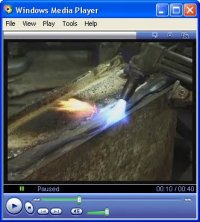
| Hot processes are used in forming, joining and cutting iron, but are often prohibited in historic buildings due to fire risk, or are allowed only on the basis of a daily hot works permit where no other process can be substituted. Coke-fired hearths were the traditional means of heating. On sites small portable hearths were employed for heating rivets, etc. and hearths are still widely used in workshops for general forgework. Nowadays three additional methods of heating are commonly in use: | |
| Fuel gas and air - Butane or propane stored in portable bottles mixes with air at a torch to provide a flame at several hundred degrees centigrade. Used for low temperature operations such as heating components to separate them, softening paint, and soft soldering. see below) | |
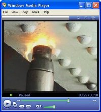
| Fuel gas and oxygen - Propane or acetylene and oxygen stored in heavy bottles mix at the nozzle of a blowpipe to produce a flame around 3,000 degrees centigrade. Used for forming metals, separating components, flame cleaning, silver-soldering, brazing and fusion welding. (see below) These gases can also be used for cutting thick sections of wrought iron and steel where excess oxygen is used to blow away white-hot metal (flame cutting). Use of gases on site is dangerous due to their flammability and naked flame, and restricted by the size and weight of bottles. | |
| Electric arc - The low voltage/high current output from a transformer provides a continuous spark or arc between the workpiece and an electrode at around 3,000 degrees centigrade producing an instant localised molten pool. Used mainly for welding processes, principally MMA & MIG (see below). Electric arc welding is not recommended for repairs to cast iron due to the risk of thermal-shock damage to the brittle material. | |
 |
Soldering & welding processes - Iron oxidises when heated which prevents
joining, or reduces the strength of the joint. A flux or inert gas shield must
therefore be introduced to prevent oxidation by providing reducing conditions.
|
 |
Hot set riveting - This is the commonest traditional method of joining wrought
iron components in structural and decorative applications, and should NOT be
replaced by welding. Rivets are entered red-hot into prepared holes, the head
retained by a hand-held gun or jack, (a holder-up) and the tail forged down to
fill the hole, and grip the components. Grip is further tightened by the rivet
shrinking, resulting in a strong, watertight joint. Rivet heads are commonly
spherical (round-head), conical (snap-head), or flush with the surface
(counter-sunk). Small rivets are set by hand, larger ones by pneumatic or
hydraulic tools which allow large numbers of rivets to be set quickly.
Removal of rivets must be undertaken with care to avoid damaging plates and holes. Heads may be ground off, shanks drilled and the rivet punched out. A quicker (traditional) method is to shear off the head with a rivet-buster, a long pneumatic gun operated by two men. Its chisel is placed under the rivet-head to shear it off, and a punch in the same gun is used to drive out the shank. Appropriate safety precautions must be taken. |
| Cold repairs avoid the thermal stresses and fire/fume-risk of hot processes,
and so are particularly suitable for repairing cast iron, and for use in
historic buildings. Cold processes also generally employ simpler/cheaper
equipment, and should be adopted in preference to hot techniques where possible.
Traditional grey cast iron contains flakes of graphite which lubricate cutting operations such as drilling and tapping (threading) holes. All the techniques described in this section are commonly used for repairing cast iron |
|
 |
Plating - A strong and discreet repair can often be achieved by bolting a steel
plate across a cracked component on a hidden face. Plates must be bedded on
red-lead or two-pack epoxy putty to exclude water, and can be secured with
counter-sunk screws for a neater appearance. If stainless steel plates or
fastenings are used they must be physically/electrically isolated from the
casting to prevent dissimilar-metals corrosion. Stainless steel bolts can be
insulated by painting with two-pack epoxy primer and assembled before the paint
cures.
Structures are increasingly being repaired or strengthened by bonding on plates of carbon or glass-fibre. (see below). Studding - Broken rod-shaped components can be repaired by drilling and tapping both parts and screwing together onto a threaded bar (studding), bedded on red-lead or two-pack epoxy putty. If components cannot be rotated, the studding can be screwed into one part and secured by epoxy putty into the other.Carbon/Glass Fibre repair/strengthening - Filaments of carbon or glass are bonded with two-pack epoxy resin onto a blast-cleaned surface to strengthen a component or repair a crack. Preformed and tensioned plates may also be used to upgrade structural strength. Stitching - A modernised traditional technique for repairing castings in which holes are drilled across a crack, slotted, and a ferrous lock or stitch is driven in to tie the sections together. Advantages: Cold process requiring only portable hand tools. Safe on site. Hermetically tight, no sealants used. Invisible on completion. Disadvantage: Not suitable for thin sections. |
©2007 University of the West of England, Bristol
except where acknowledged