Iron and Steel
5 Wrought Iron - Beams & Riveting
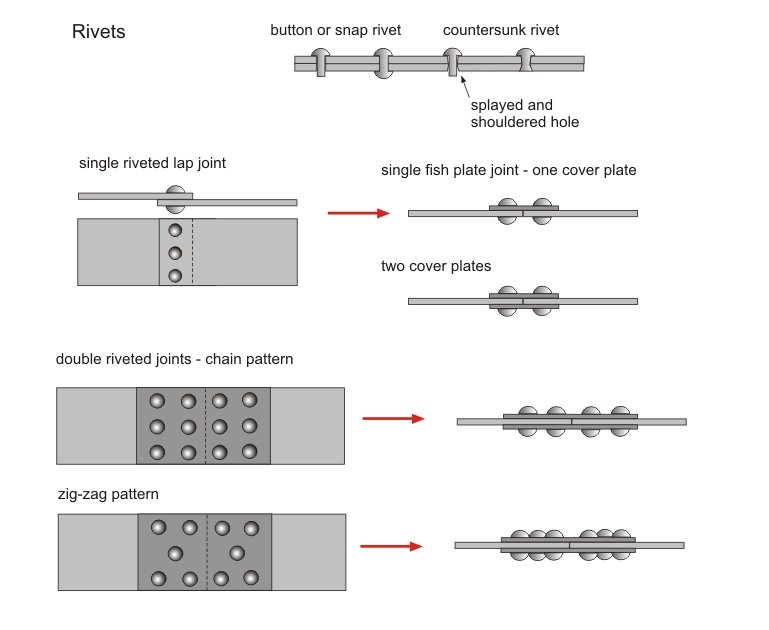 |
Most wrought iron work was joined by riveting. This gave a much stronger and more reliable joint than bolting. In the mid 19th century riveting was usually carried out by hand although by the end of the century hydraulic and pneumatic riveters were available - the latter gave a better and more consistent joint. The rivet was heated until red hot and then hammered close to the face of the plate. As the rivet cooled it contracted and drew together the face of the plates. Rivets were made from good quality wrought iron (steel work later in the century was also riveted - but with steel rivets). The pitch of the rivets (centres) was typically 3" to 5" (75 to 125mm) and the shank diameter was typically 1" if joining ½" plates. (wider for thicker plates). The holes (slightly larger than the cold rivet) in the plates were punched or drilled. Joints were lapped or 'fished' with cover plates. | |
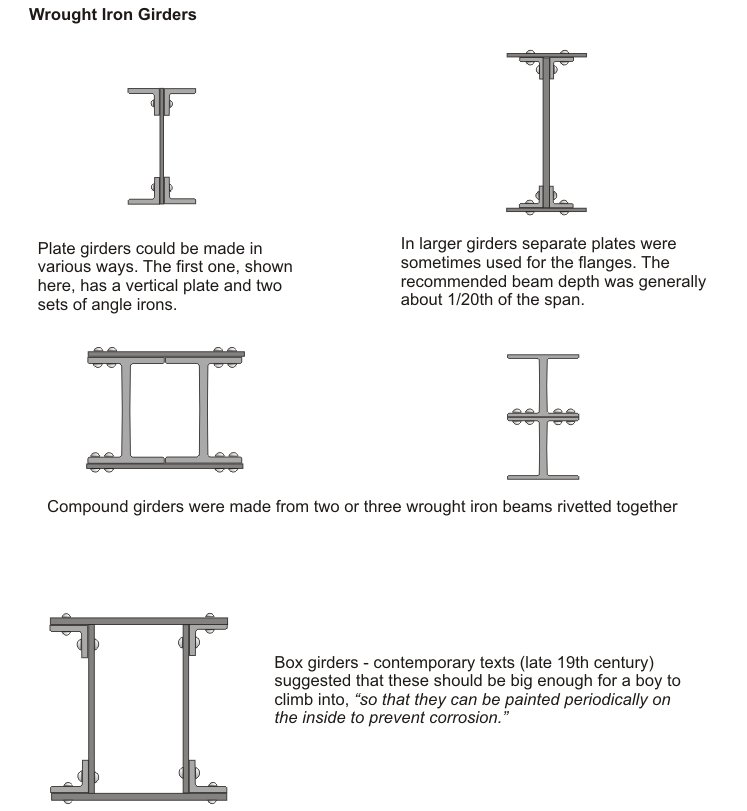 |
When wrought iron first became relatively common (mid 19th century) there were limits on the sizes of beams that could be successfully rolled. To get over this problem beams were made from angle sections and flat plates riveted together. They could also be made by 'compounding' smaller beams. This in fact offered a number of advantages - the components could be more readily transported to site and, as Rivington stated in his 'Building Construction' (originally published in 1875); ..."the number and thickness of the plates used in a built-up girder may be varied at different parts of it, in proportion to the stresses which come upon those parts; whereas in a rolled girder, the thickness of the web and of the flanges is necessarily unvarying throughout, and if, therefore, these are thick enough to withstand the greater stresses, they are too thick in those portions where the smaller stresses occur." | |
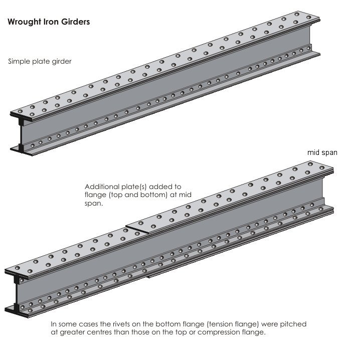 |
A simple rolled wrought iron 'I' beam or a simple plated girder was
generally assumed to have a span capability of about 20 times its depth.
For greater spans or where loads were expected to be particularly high
the flanges could be reinforced by adding extra plates top and bottom.
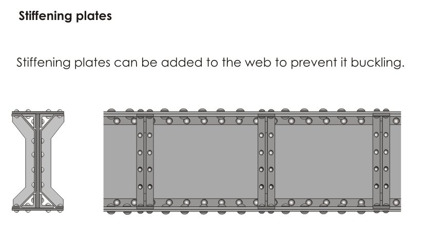
If the beams had a deep web (i.e. large compound beams designed to cope with very high loads) there was the danger that the web could buckle under load. This was resisted by reinforcing the web with stiffeners, usually 'T' sections riveted to both sides of the web. |
 |
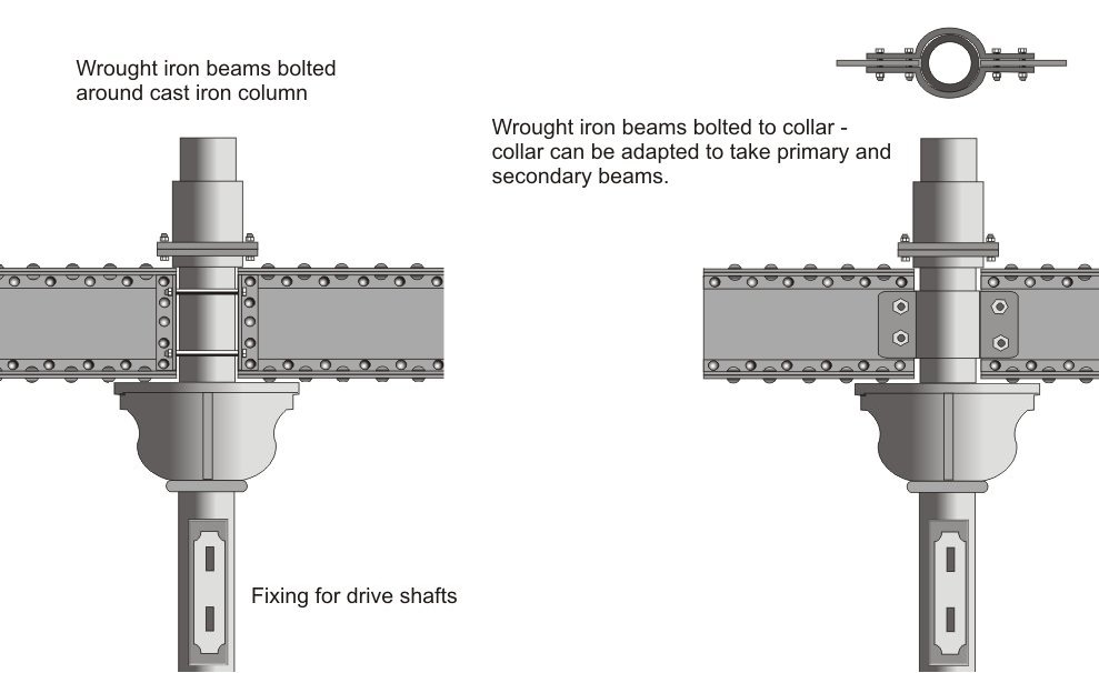 |
Wrought iron was much more expensive to produce than cast iron and, in fact, not as strong in compression. The manufacture of cast iron columns, therefore, continued well into the 20th century. A wrought iron beam could be connected to a cast iron column in a number of ways - two are shown in the left-hand graphic (neither of them use rigid fixings as described in the first page of this section). Wrought iron beams, despite their many advantages were not common in textile mills. In fact, many mill designers 'by-passed' wrought iron, making the jump from cast iron to steel beams towards the end of the 19th century. | |
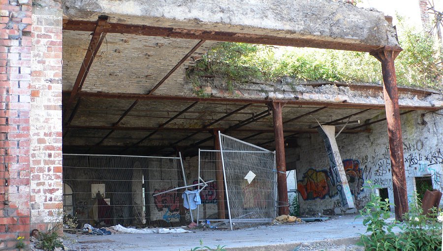 |
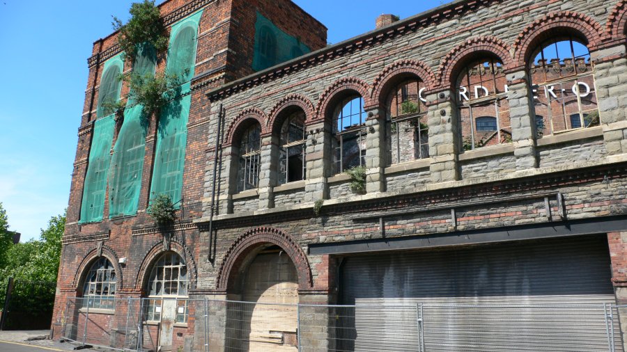
Although many mill designers were slow in exploiting the capabilities of wrought iron others were quick to spot its potential. The building shown here (Bristol), originally a soap works built in 1865, has been in a partly demolished state for several years. The partial demolition has exposed an interesting floor structure. This comprises wrought iron plated girders with a brick arch infill supported by the external loadbearing walls and, internally, by cast iron columns. Note that the top and bottom flanges of the girder (look at the one in the background - left-hand picture) are not parallel. |
 |
except where acknowledged