Iron and Steel
3 Cast Iron - Columns & Beams
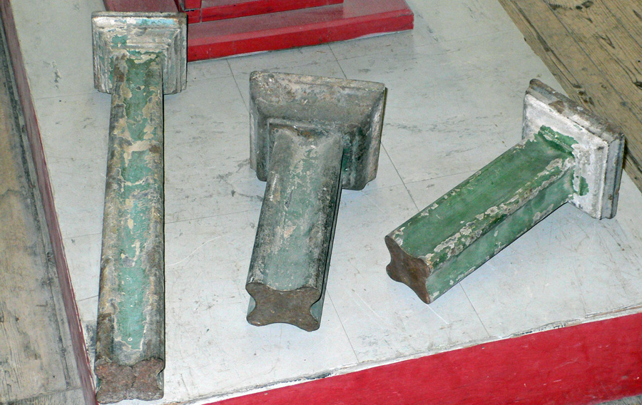 |
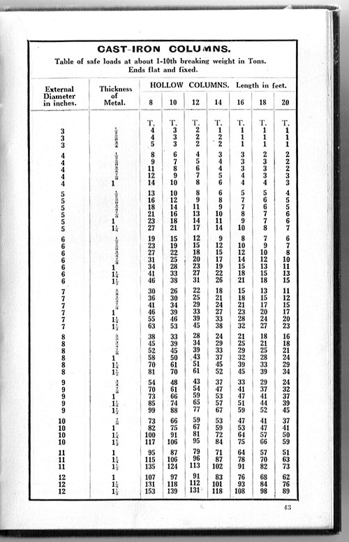
Hollow castings such as columns were carried out in much the same way as described on the previous page but with an inner core of sand forming the 'hollow'. Columns were often cast vertically to help compaction of the metal (this also helped to exclude bubbles etc) and to ensure that the metal was of uniform thickness all round. The image on the left shows some early solid cruciform column castings (c1800). During the 19th century cylindrical columns became the norm and they were usually hollow. As late as the mid 1920s cast iron columns were still readily available. The chart on the right shows the size and load bearing capabilities of a variety of cast iron columns; the table is taken from the Chas Wade catalogue 1926. |
 |
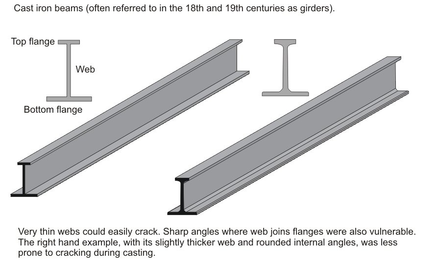 |
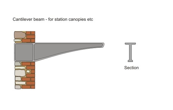
Cast iron has good compressive strength but relatively poor tensile strength. Its average ultimate tensile strength was 9 tons per sq inch and its compression strength 48 tons per sq inch (figures from Rivington's Building Construction 1904). However, producing a good casting was often a bit of a 'hit and miss' affair; as a result big safety factors were adopted. Its safe working strength was generally taken as 1.5 tons sq inch (tension) and 8 tons sq inch (compression). Engineers of the time assumed that the difference in tensile and compressive strength should be reflected in the beam's design. As a result it's quite common to find early beams with small top flanges and wide bottom ones (reversed in cantilever beams - see right). |
 |
 |
In practice the top flange is often quite wide to stop lateral movement of the beam and to provide an adequate fixing for anything on top of it. Engineers also realised that because the stresses from loading were greatest at the centre of the girder, the centre section should be stronger and therefore bigger in cross sectional area than the ends. In practice beams can be found in a variety of shapes and it's not uncommon to find ones which don't conform to some of the principles mentioned above. The beam shown on the left dates from the 1850s. It shows a beam which tapers slightly at each end but with top and bottom flanges pretty similar in size. Note how the beams are joined to the columns; this arrangement, with lugs on the end of the beams bolted around the columns, was fairly common during the 19th century. | |
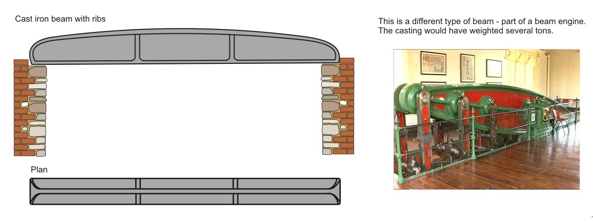 |
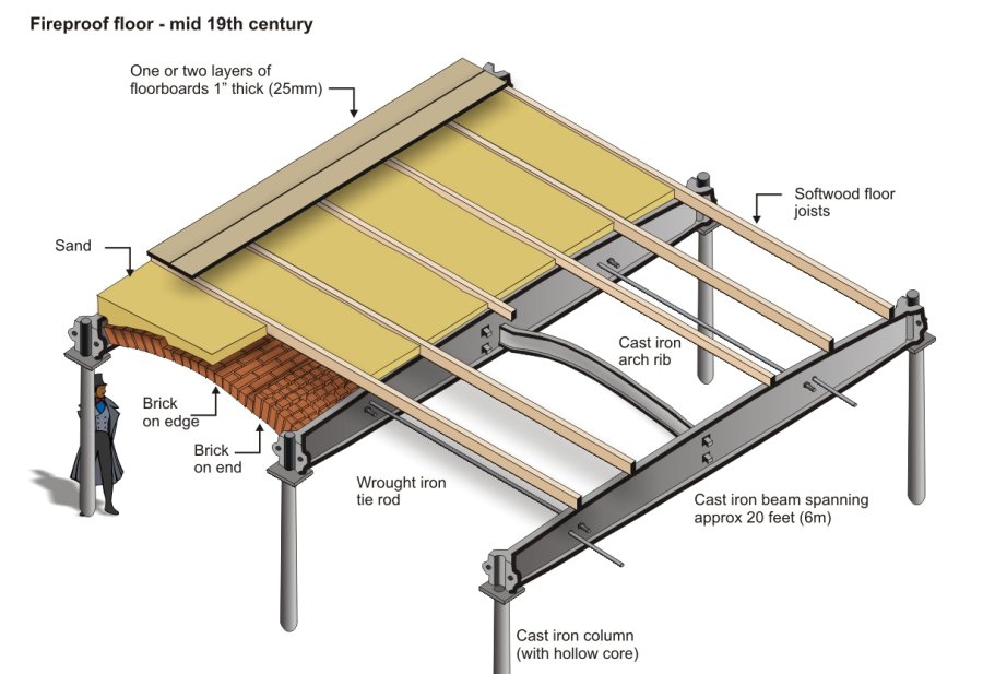
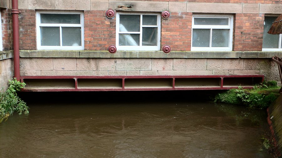
Vertical ribs or 'feathers' were sometimes cast into girders to act as stiffeners. The graphic on the left shows a typical early beam designed to carry a fairly substantial load. The example on the right shows a slightly different design of ribbed cast iron girder carrying part of Masson Mill over the mill race. A number of these girders were used, laid side by side. Some 19th century textbooks suggest that cast iron girders should be limited to a span of about 20 feet (6 metres) and that the depth of the girder should ideally be about 1/12th of the span. |
 |
 |
Armley Mill in Leeds is a good example of an early mill which
incorporates cast iron in its structure. There have been mills on this site since the 17th
century,
although the present building dates from 1805. Benjamin Gott, a major
figure in the industrial development of Leeds bought Armley Mill from Thomas Lloyd (a cloth merchant),
but had to rebuild it the following year after it was almost entirely destroyed by fire. Gott re-built the mill
using 'fireproof' materials wherever possible, i.e. brick for the external walls, and iron
and brick for the floors. Gott became one of
the biggest and wealthiest employers in Yorkshire and when he died in 1840 his sons, John
and William, took over the mills and continued to develop the family's
textile interests. It was they who installed a steam engine in 1850. The mill survives largely intact to
this day although cloth manufacture has long since ceased; it's now an industrial museum run by Leeds City Council.
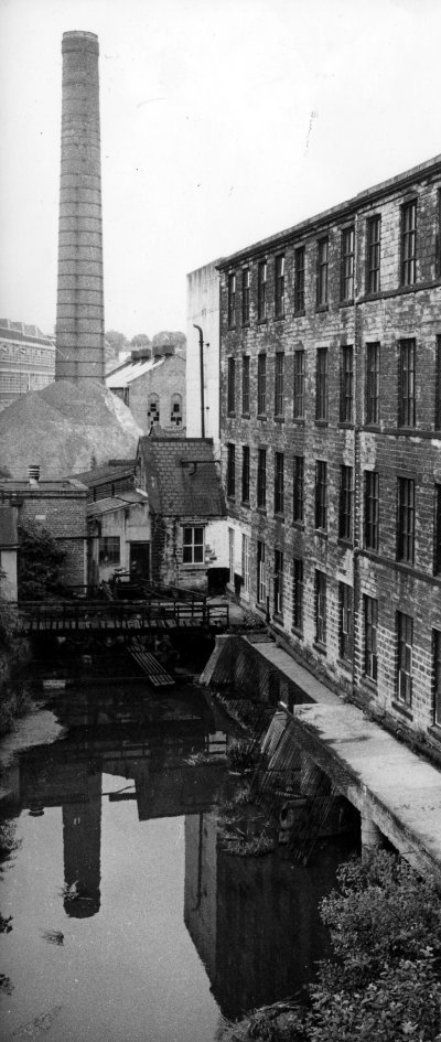
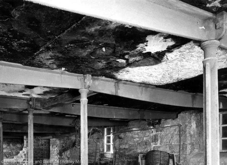
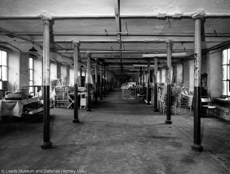
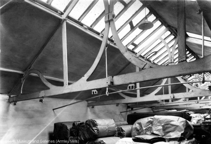
The left-hand picture (all pictures are from the mid 1970s) shows part of the factory and the goit at Armley. The goit (head race) provided a channel directing part of the river over the water wheel; the chimney behind it was not built until the arrival of steam. The top right-hand image shows the interior of the corn mill built in the 1790s at Armley Mills. At this time Armley was noted for its corn as well as its fulling mills. It has cast iron columns and beams - note that the beams are slightly convex (deeper near their mid span) but without a bottom flange.The middle picture shows the fireproof structure of the main block of Armley Mills (picture taken on second floor). This construction is explained in more detail in a later section. The bottom picture shows the cast iron roof trusses of a drying shed; original clips can be seen on the trusses. Cast iron roof trusses are comparatively rare - wood remained the choice of most mill designers for roof structures until quite late in the 19th century when it was replaced by wrought iron and steel - sometimes with cast iron for the compression elements. A later section explains the evolution of iron and steel roofs. |
 |
 |
||
 |
||
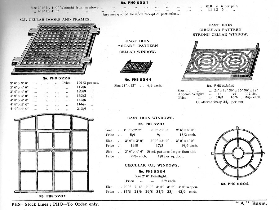 |
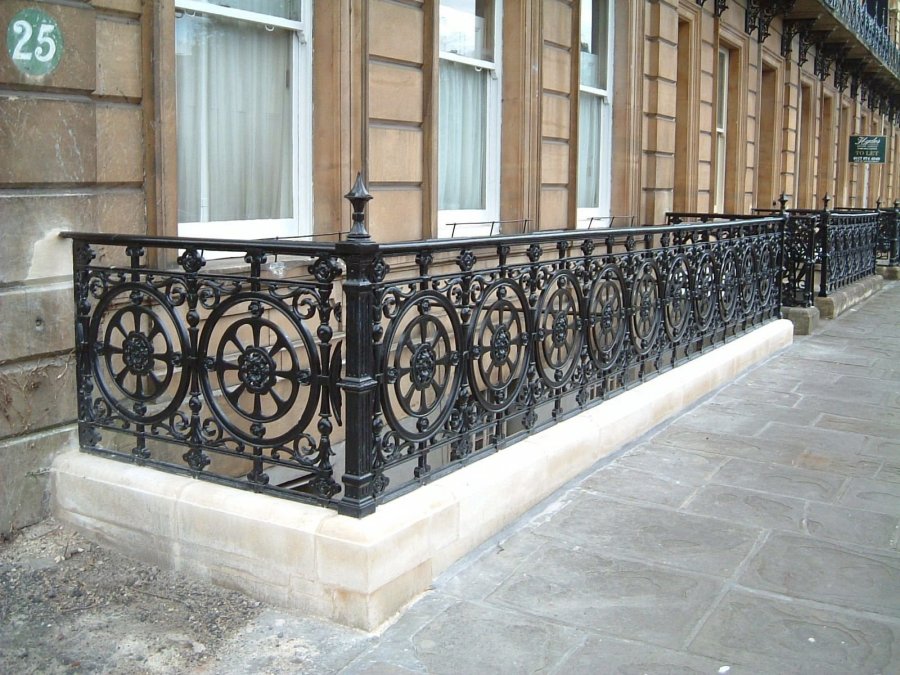
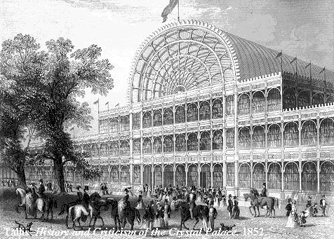
Cast iron was used to make hundreds of products besides columns, beams
and roof trusses. These included, amongst many others, inspection
covers, gratings, lamp posts, windows, guard rails, gates, fences, and
fire escapes. Crystal Palace, designed by Joseph Paxton and Charles Fox, was built to house the Great Exhibition (Hyde Park, London 1851). The structure was based on Paxton's experience designing greenhouses for the Duke of Devonshire and was made from glass, cast iron and wrought iron (see below). Nearly all the components were made in Birmingham and Smethwick. The huge structure was 1848 feet long (approx. 560 metres) and 454 feet wide (approx 135 metres). After the Exhibition the building was taken down and re-erected at Sydenham, south London, an area that became known as Crystal Palace. It was destroyed in a fire in 1936. |
 |
except where acknowledged